












Product Details
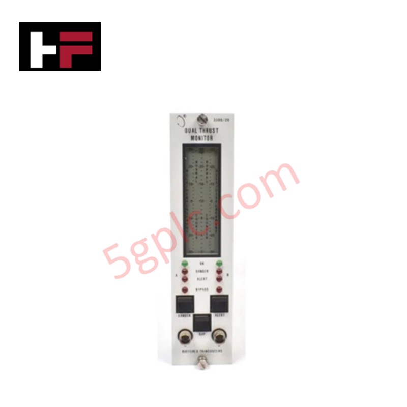
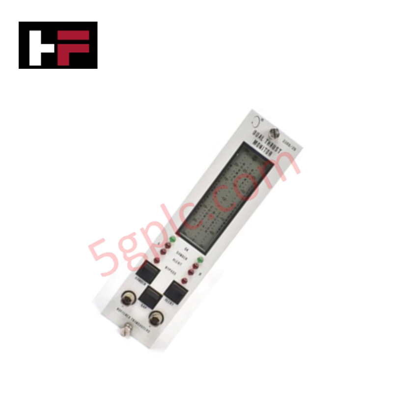
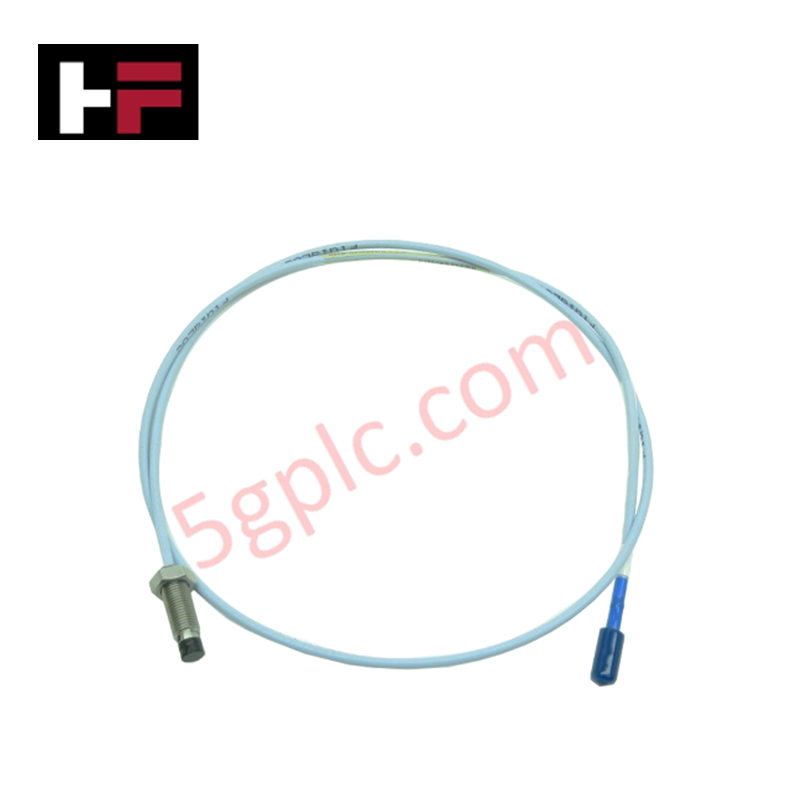
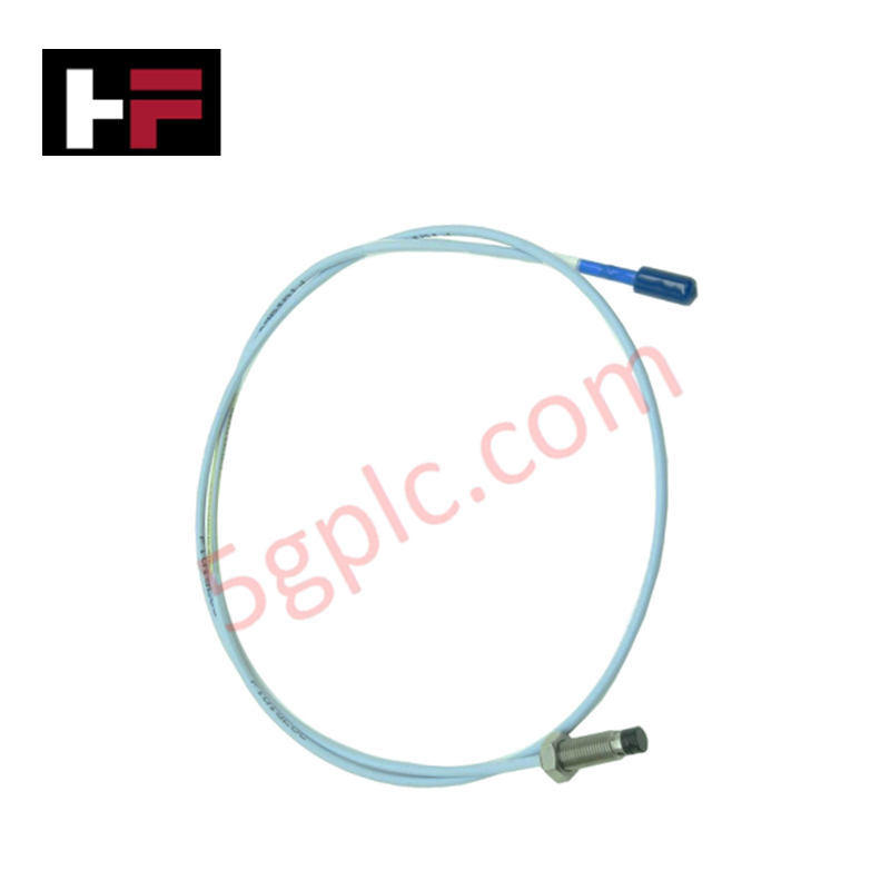
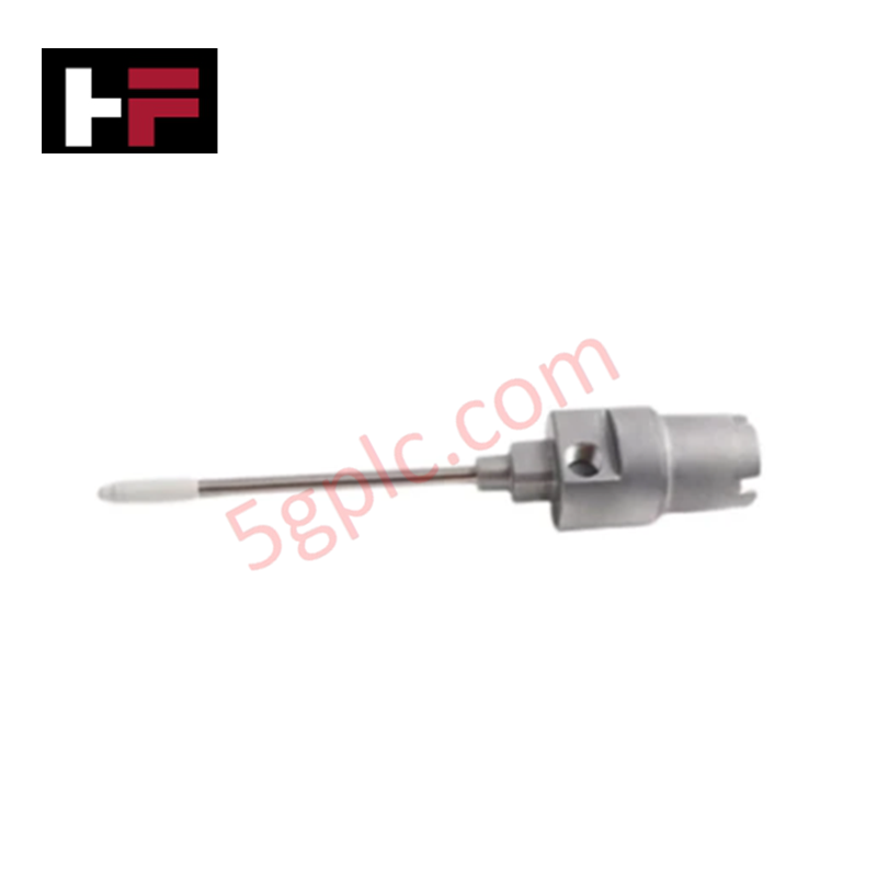
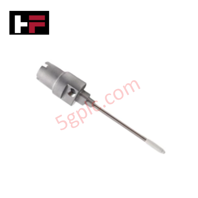
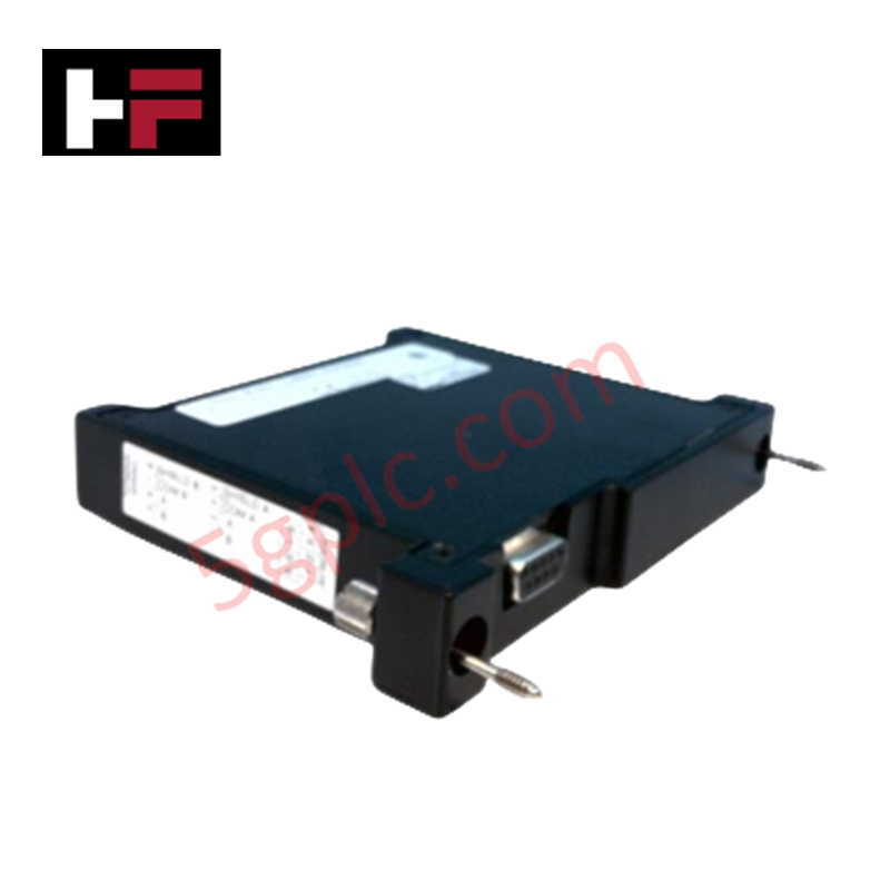
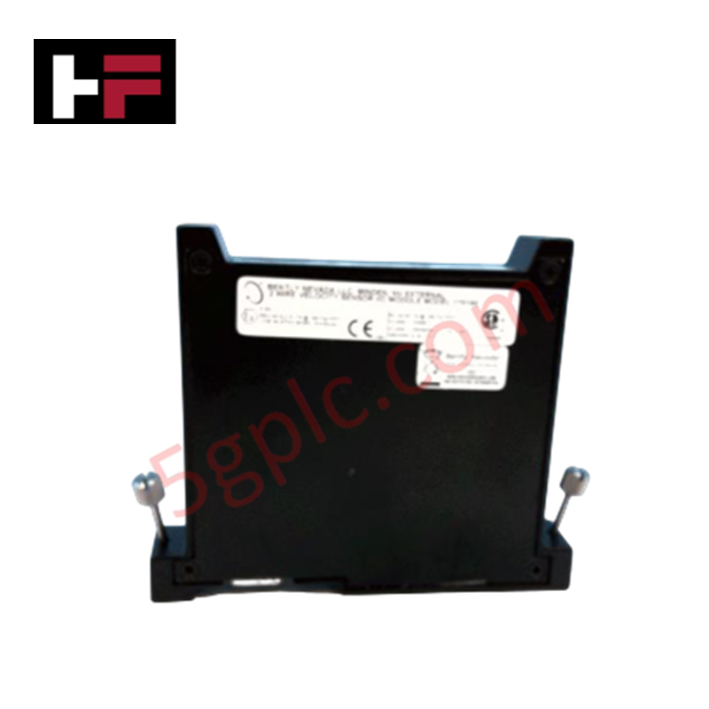
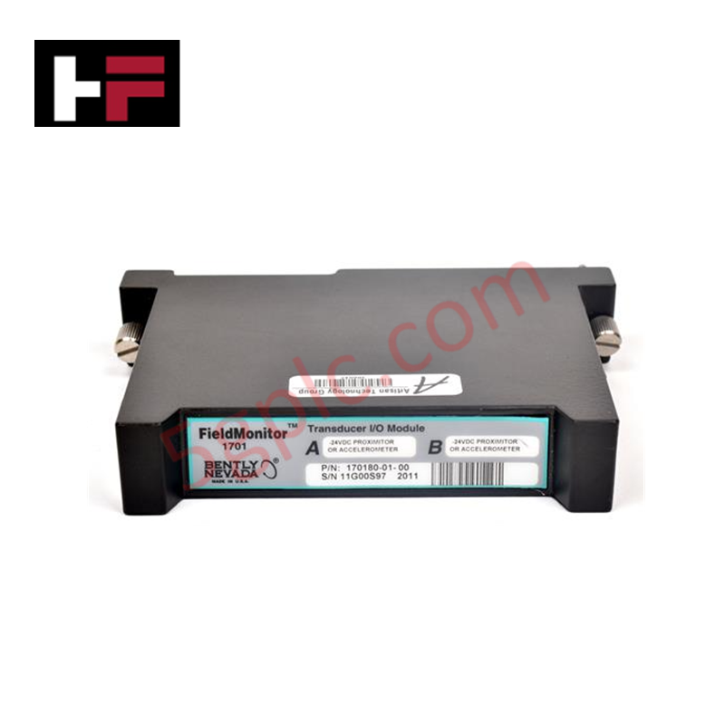
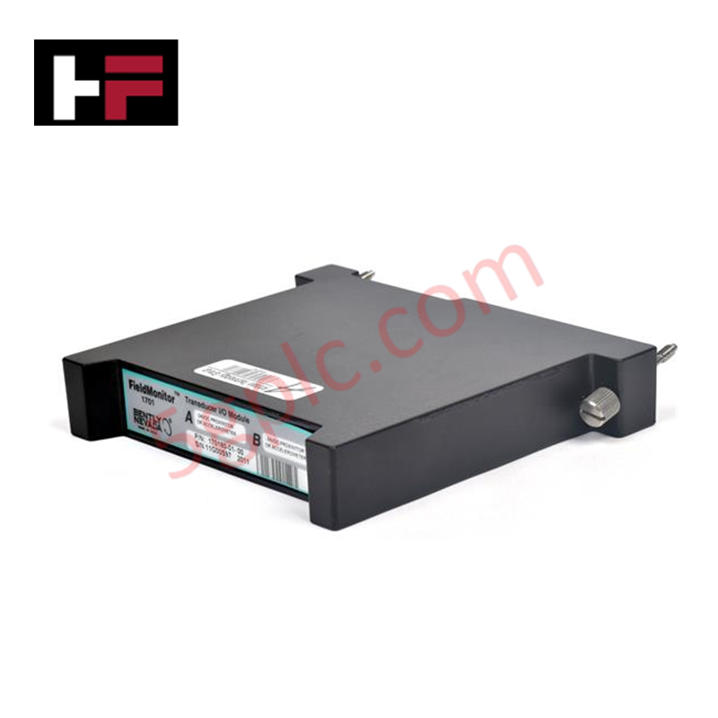
Configured for vibration and shaft position acquisition in Bently Nevada monitoring platforms, the Bently Nevada 3800A03-50-00 (3800A03 Industrial Monitoring Module) provides direct physical/electrical execution.
Suffix Breakdown & Model Matrix
| Option Field | Code | Configuration Detail |
|---|---|---|
| Main Module Base | 3800A03 | Standard 3800 Series industrial vibration monitoring core architecture |
| Channel Configuration | 50 | 50-series hardware and signal input options |
| Agency / Option Code | 00 | Standard uncertified configuration / baseline options |
Hardware Specifications
| Parameter | Specification |
|---|---|
| Model | 3800A03-50-00 |
| Brand | Bently Nevada |
| Origin | USA |
| Weight | 1.2 kg |
| Dimensions | 190 cm x 16.2 cm x 10.8 cm |
| Operating Temp | -20 deg C to +65 deg C |
| Power Consumption | Powered via system backplane assembly |
| Measurements | Dynamic vibration and shaft position telemetry |
| Outputs | Configurable alarm thresholds, discrete relay outputs |
| Data Handling | Real-time acquisition and signal analysis |
Rotor Dynamics and Signal Conditioning Execution
The 3800A03-50-00 module executes real-time dynamic signal acquisition from proximity probes and seismic velocity transducers to analyze rotor dynamics across rotating machinery. Internal analog-to-digital processing calculates peak vibration amplitudes and shaft centerline displacement. Integrated output logic monitors signal limits against user-configurable alarm thresholds, driving physical relay contact state execution for machinery protection systems while maintaining low channel-to-channel cross-talk.
Frequently Asked Questions
Q: How are alarm thresholds and physical relay outputs controlled within the 3800A03-50-00?
A: Alarm logic monitors incoming raw analog signals continuously against digitally programmed setpoints. When thresholds are breached, internal dry-contact relays switch state to trigger external safety interlocks or annunciators.
Q: Can the module be inserted or removed while the rack backplane is energized?
A: Rack power should be turned off before inserting or pulling the module to prevent electrical transients across backplane signal connectors and preserve internal calibration settings.
Field Installation Guidelines
- Power down the system rack before inserting the 3800A03-50-00 module into its designated rack slot.
- Align the module card edges carefully with the top and bottom chassis guide rails inside the enclosure.
- Slide the unit inward until the rear edge connector fully seats into the backplane socket.
- Secure the front panel retaining screws using appropriate hand tools to ensure solid chassis frame grounding.
- Terminate transducer wiring with shielded twisted-pair cables, bonding cable shields to system ground at one end only to prevent ground loops.
Additional Information
- 100% Genuine Parts: All products are original and authentic, ensuring reliable industrial performance.
- 30-Day Refund Guarantee: Return any in-stock item within 30 days in original, unopened packaging for a full refund (excluding shipping and fees).
- 12-Month Warranty: Covers defects in materials or workmanship; excludes misuse, normal wear, or unauthorized modifications.
- Worldwide Shipping: We ship via USPS, UPS, FedEx, and DHL. Delivery times vary by country and may be subject to customs or import fees.
- Support & Contact: Technical and warranty assistance is available anytime. Contact us here: Contact.
- Purchase Guidance: Check product specifications and compatibility carefully before ordering to ensure proper application.

Tech & Buying Guide
Mastering Modern Industrial Joystick Controls in Heavy Automation
Industrial joysticks play a pivotal role in human-machine interaction across heavy material handling and mobile hydraulics. These tactile controllers translate complex operator movements into precise electrical signals for PLCs, motion controllers, and DCS networks. Consequently, selecting and installing the right joystick architecture ensures operator safety, reduces fatigue, and optimizes equipment performance.

Navigating Industrial Automation Failures: Types, Causes, and Mitigation Strategies
Modern manufacturing relies heavily on automated control systems to maximize throughput and maintain product quality. However, unplanned downtime in industrial automation can cost facility operators thousands of dollars per hour. Understanding how programmable logic controllers (PLCs), distributed control systems (DCS), and field instrumentation fail empowers engineering teams to implement robust preventive maintenance strategies.
Essential Motion Control Commands: A Practical Guide for Engineers
Automation engineers often rely on precise position and speed control to drive modern factory machinery. Modern industrial systems, such as Programmable Logic Controllers (PLCs) and Distributed Control Systems (DCS), depend heavily on standardized motion instructions. Mastering these commands ensures operational safety, protects mechanical components, and optimizes cycle times across production lines.