












Product Details
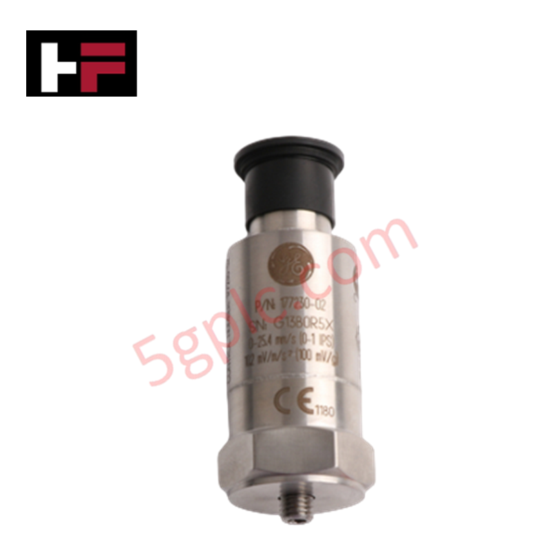
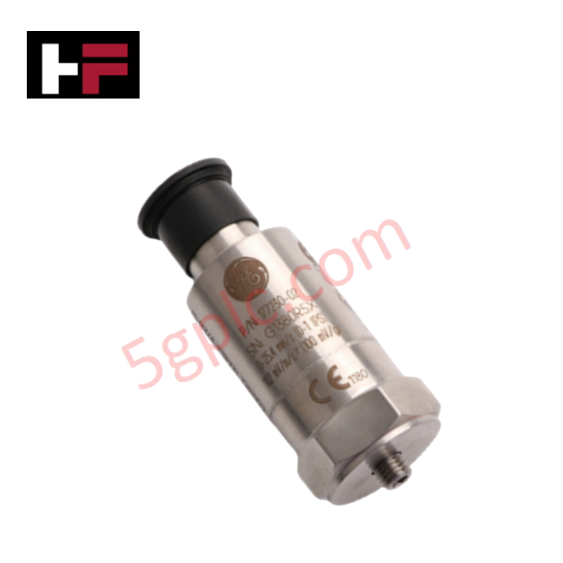
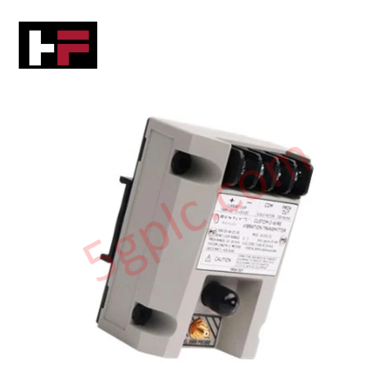
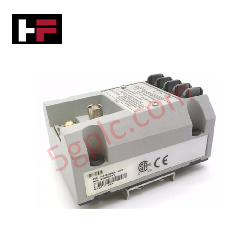
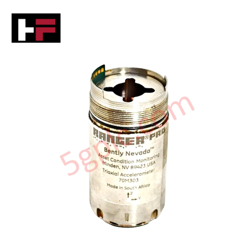
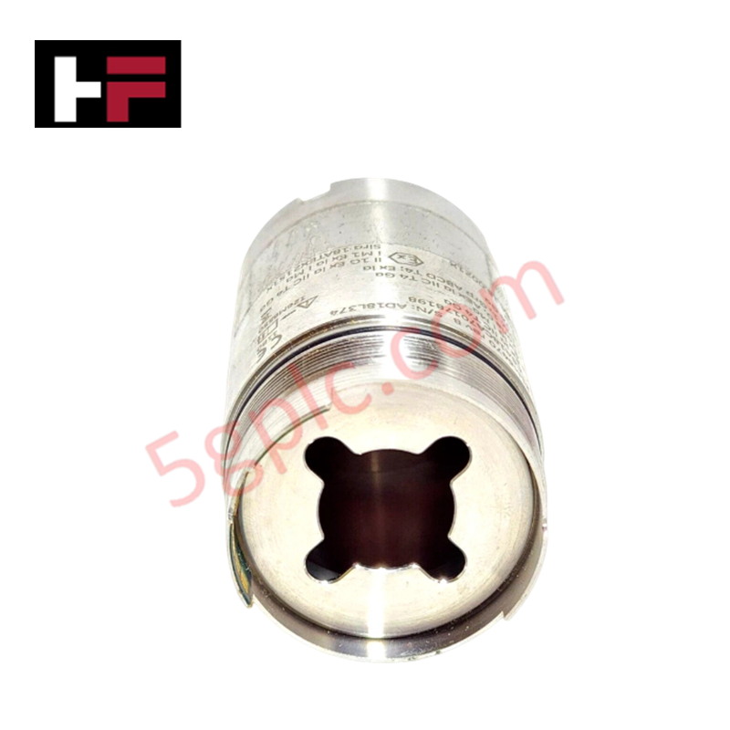
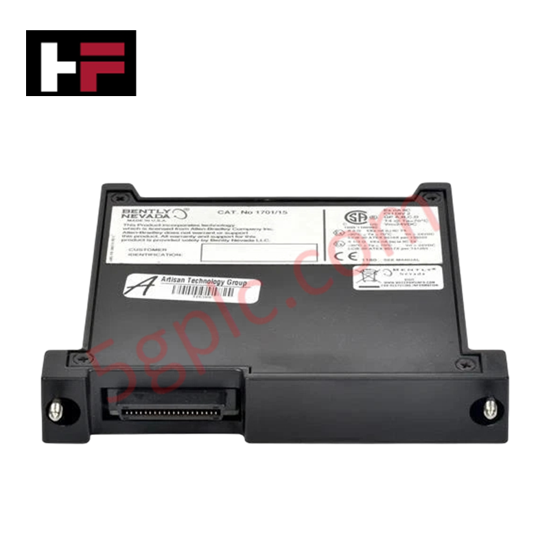
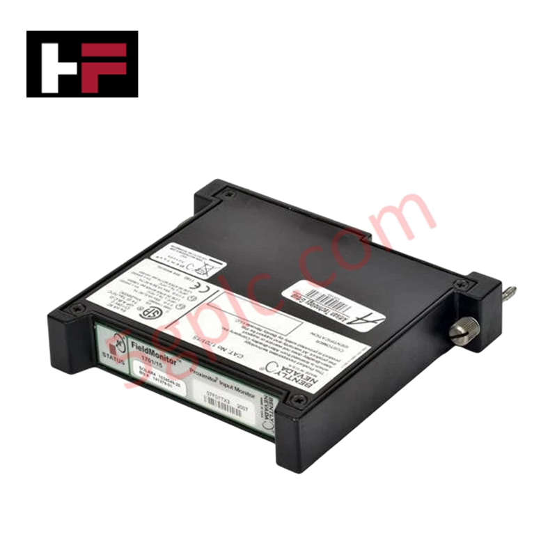
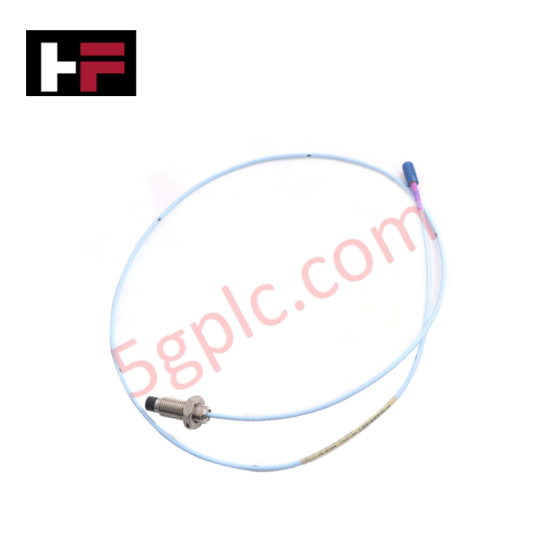
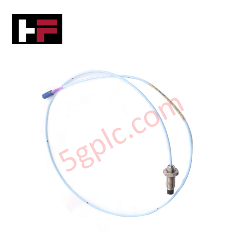
Configured for dynamic vibration monitoring and overall velocity signal acquisition in machinery protection platforms, the Bently Nevada 177230-02 (177230 Seismic Transmitter) provides direct physical/electrical execution.
Hardware Specifications
| Parameter | Specification |
|---|---|
| Model | 177230-02 |
| Brand | Bently Nevada |
| Origin | USA |
| Weight | 0.131 kg (Shipping weight: 1.5 kg) |
| Dimensions | Height: 66.0 mm (2.60 in), Diameter: 25.4 mm (1.00 in) |
| Operating Temp | -40 deg C to +85 deg C (-40 deg F to +185 deg F) |
| Power Consumption | Loop-powered via 4-20 mA current loop |
| Measurement Range | 0 to 50.8 mm/s (0 to 2.0 in/s) |
| Connector Type | 3-pin MIL-C-5015 |
| Case Material | 316L Stainless Steel |
| Electrical Isolation | Greater than 10^9 ohms |
Rotor Dynamics and Seismic Signal Processing
The 177230-02 seismic transmitter integrates solid-state piezoceramic sensing elements and conditioning electronics to evaluate rotor dynamics and structural casing vibration. Internal signal processing converts raw acceleration forces into a peak-velocity 4-20 mA current loop signal proportional to the specified 0 to 50.8 mm/s (0 to 2.0 in/s) vibration amplitude. Electrical isolation exceeding 10^9 ohms prevents ground loops and suppresses parasitic signal cross-talk between adjacent sensor channels on rotating machinery housings.
Frequently Asked Questions
Q: How is signal loop integrity maintained over long cable runs?
A: The transmitter utilizes a 4-20 mA loop-powered topology over its 3-pin MIL-C-5015 connector interface, minimizing voltage drop attenuation and EMI noise susceptibility over extended field wiring lengths.
Q: What is the isolation capability between the internal circuit and the transmitter housing?
A: The internal transducer circuitry provides galvanic and physical isolation exceeding 10^9 ohms relative to the 316L stainless steel outer casing.
Field Installation Guidelines
- Mount the transmitter vertically onto a smooth, flat, machined metal surface on the bearing housing using a dedicated threaded stud.
- Ensure the mounting surface is free of paint, corrosion, and surface irregularities to maintain solid physical contact for accurate high-frequency transmission.
- Torque the transducer mounting stud to standard engineering limits (typically 3.4 N-m to 6.8 N-m) to prevent housing distortion or resonance decoupling.
- Align and mate the 3-pin MIL-C-5015 cable connector assembly onto the transmitter top header, fully tightening the threaded coupling nut.
- Cable shielding must be connected to ground at one end only—typically at the control system rack ground—to prevent ground loop noise from corrupting loop telemetry.
Additional Information
- 100% Genuine Parts: All products are original and authentic, ensuring reliable industrial performance.
- 30-Day Refund Guarantee: Return any in-stock item within 30 days in original, unopened packaging for a full refund (excluding shipping and fees).
- 12-Month Warranty: Covers defects in materials or workmanship; excludes misuse, normal wear, or unauthorized modifications.
- Worldwide Shipping: We ship via USPS, UPS, FedEx, and DHL. Delivery times vary by country and may be subject to customs or import fees.
- Support & Contact: Technical and warranty assistance is available anytime. Contact us here: Contact.
- Purchase Guidance: Check product specifications and compatibility carefully before ordering to ensure proper application.


Tech & Buying Guide

Step-by-Step System Cabinet Health Check Guide for PLC and DCS Infrastructure

Top 5 Operational Advantages of HMIs in Modern Factory Automation
