










Product Details
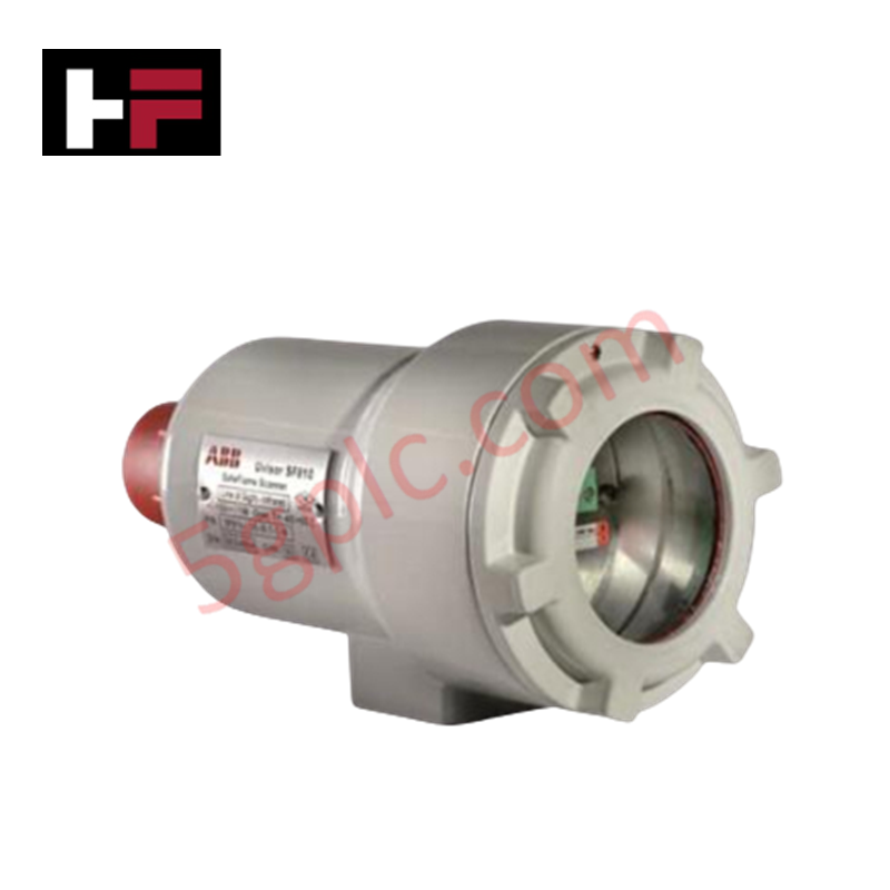
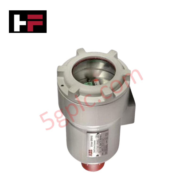
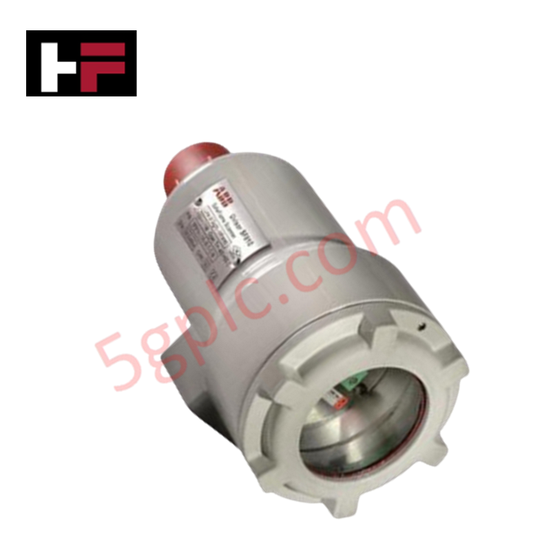
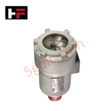
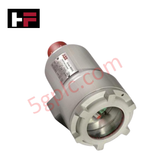
The ABB SF810-FOC-IR-TL-C-W, also cataloged as the SF810 SafeFlame Scanner, operates as a dedicated hardware component for infrared flame radiation detection within SafeFlame monitoring assemblies. The sensor head utilizes an integrated IR sensing element and a 3/4-inch NPT threaded connection to capture dynamic optical flame signals and transmit raw radiation intensity data to primary burner management circuitry.
Hardware Specifications
| Parameter | Specification |
|---|---|
| Model | SF810-FOC-IR-TL-C-W |
| Brand | ABB |
| Origin | Sweden |
| Power Consumption | Powered via scanner control interface |
| Sensor Type | Infrared (IR) sensor head |
| Mounting Thread | 3/4 in thread |
| Product Type | Flame Scanner Heads |
| Signal Output | Dynamic flame spectral intensity signal |
Deterministic Network Architecture and Control Execution
The SF810-FOC-IR-TL-C-W scanner head processes optical infrared modulations to discriminate targeted flame spectra from background refractory radiation. Its physical signal link integrates directly with control backplanes, supporting Profinet / EtherNet/IP deterministic networks and high communication velocity requirements across burner management racks.
Firmware flash compatibility and hardware signal conditioning ensure instantaneous flame discrimination response. Channel-level isolation prevents electrical noise along the sight pipe from corrupting backplane communication velocity or triggering nuisance burner trip sequences during steady-state combustion cycles.
Frequently Asked Questions
Q: What optical sensing spectrum is utilized by the SF810-FOC-IR-TL-C-W scanner head?
A: The scanner head incorporates an infrared (IR) sensor designed to target optical radiation modulations emitted by combustion flames.
Q: What mechanical connection thread is integrated into the scanner housing for installation?
A: The unit features a standard 3/4-inch threaded mounting connection for secure mechanical engagement to sight pipes.
Q: How is signal processing handled between the optical sensor and the control network?
A: The optical signal is conditioned at the sensor level before being routed to processing modules that interface with deterministic control backplanes.
Field Installation Guidelines
- Inspect the 3/4-inch thread interface for debris and ensure at least 5 full threads of engagement when screwing the scanner onto the sight pipe assembly.
- Position sight pipes to align directly with the target flame core while avoiding direct viewing of high-temperature background refractory surfaces.
- Connect flexible fiber-optic cables or signal leads without exceeding specified bend radius limits to prevent optical transmission losses.
- Ground the outer cable shielding bar at the control panel chassis end only to prevent ground loop interference along the signal path.
- Purge cooling and sight-pipe air lines routinely to keep the front optical lens free from oil soot and particulate buildup.
Additional Information
- 100% Genuine Parts: All products are original and authentic, ensuring reliable industrial performance.
- 30-Day Refund Guarantee: Return any in-stock item within 30 days in original, unopened packaging for a full refund (excluding shipping and fees).
- 12-Month Warranty: Covers defects in materials or workmanship; excludes misuse, normal wear, or unauthorized modifications.
- Worldwide Shipping: We ship via USPS, UPS, FedEx, and DHL. Delivery times vary by country and may be subject to customs or import fees.
- Support & Contact: Technical and warranty assistance is available anytime. Contact us here: Contact.
- Purchase Guidance: Check product specifications and compatibility carefully before ordering to ensure proper application.









Tech & Buying Guide
Comprehensive Guide to PLC Types in Modern Industrial Automation
Modern industrial automation relies on programmable logic controllers to govern critical factory operations. System integrators classify PLCs based on scale, hardware architecture, and power supply design. Understanding these core categories enables automation engineers to select the right control system architecture. Consequently, proper hardware selection optimizes performance while minimizing long-term operational costs.

Demystifying the DDE Protocol in Legacy Industrial Automation Systems
Modern control systems rely heavily on seamless interprocess communication to exchange operational data between software programs. Microsoft first introduced the Dynamic Data Exchange (DDE) protocol in 1987 to enable real-time data sharing. In factory automation, DDE served as an early bridge between control software and Windows desktop applications. Therefore, understanding DDE mechanics provides crucial insights into how legacy industrial networks established software-level connectivity.

Demystifying CPU Communication Ports in Siemens PLC Architectures
Industrial automation relies heavily on robust data exchange between devices. Without seamless connectivity, field instruments, network switches, human-machine interfaces, and programmable logic controllers cannot coordinate effectively. Therefore, understanding the various CPU communication ports available in Siemens hardware ensures efficient factory automation design and seamless system integration.