








Product Details
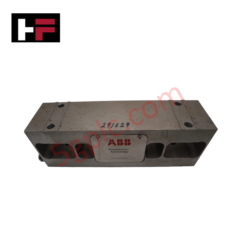
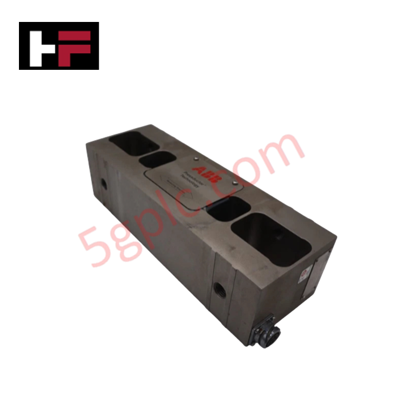
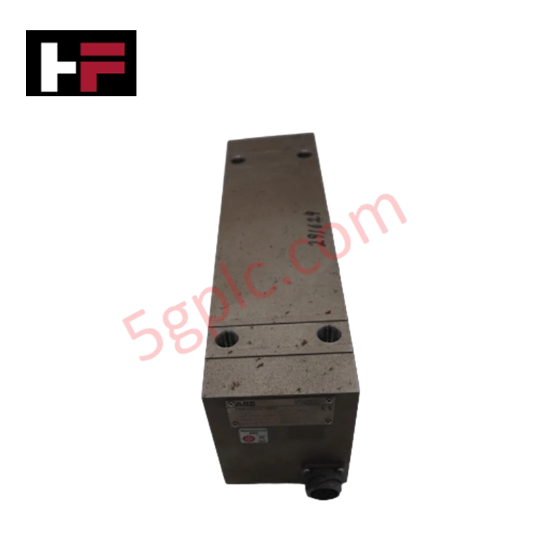
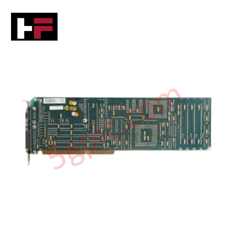
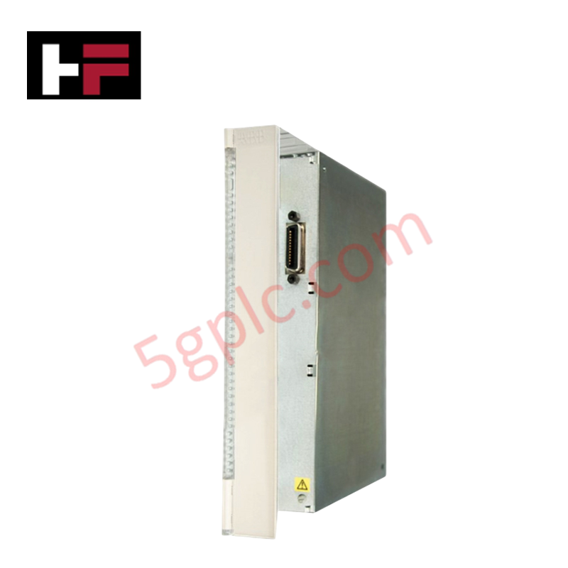
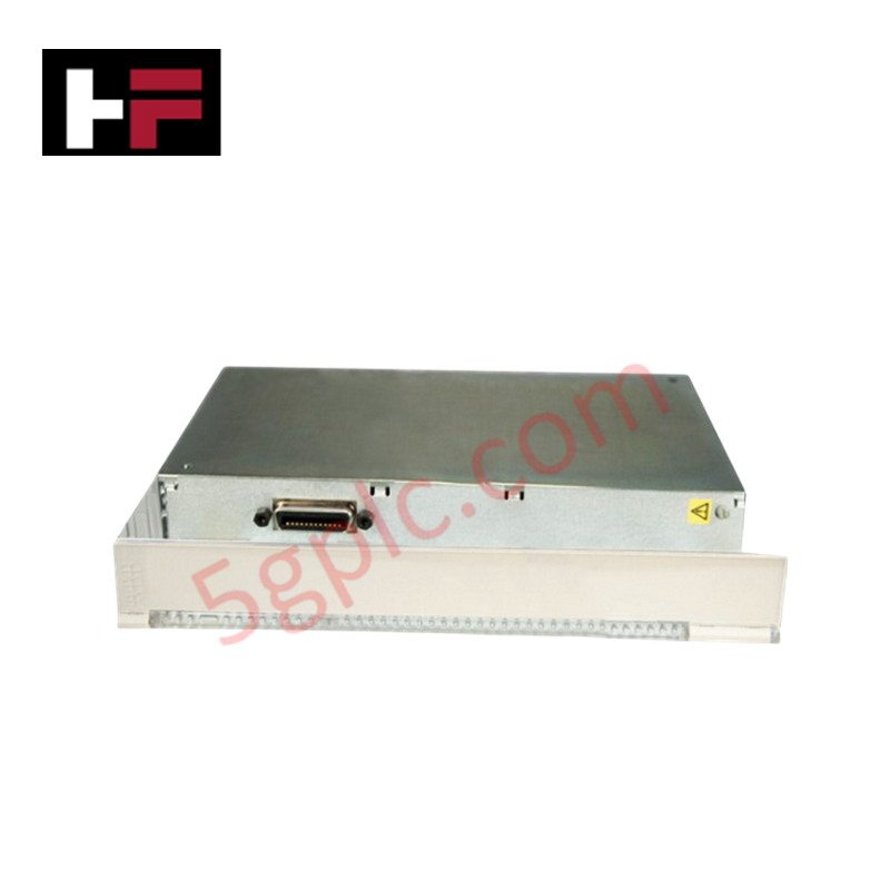
The ABB PFTL101B 3BSE004191R1, also cataloged as the PFTL101B Load Cell, operates as a dedicated hardware component for tension measurement, weight monitoring, and force detection within ABB Pressductor processing platforms. Utilizing magnetoelastic Pressductor sensor technology, the unit converts applied mechanical forces across a 0 to 5.0 kN measuring range into a 2 mV/V electrical output signal with an accuracy of +/-0.1% of full scale. Powered by an excitation voltage of 10 to 30 V DC, the stainless steel and alloy steel housing provides IP67 protection across an operating temperature range from -10 deg C to +50 deg C.
Hardware Specifications
| Parameter | Specification |
|---|---|
| Model | PFTL101B (3BSE004191R1) |
| Base Model | PFTL101B |
| Brand | ABB |
| Origin | Sweden |
| Weight | Compact Chassis Load Cell Weight |
| Dimensions | Compact Subrack / Pillow Block Form Factor |
| Operating Temp | -10 deg C to +50 deg C |
| Power Consumption | Driven by 10 to 30 V DC Excitation Voltage |
| Measuring Range | 0 to 5.0 kN |
| Measurement Accuracy | +/-0.1% of full scale |
| Output Signal | 2 mV/V |
| Housing Material | Stainless steel and alloy steel |
| Ingress Protection | IP67 |
| Sensing Technology | Magnetoelastic Pressductor principle |
Backplane Bus Communication Velocity and Firmware Flash Compatibility
The raw millivolt signal generated by the load cell routes to connected ABB evaluation units, maintaining rapid backplane bus communication velocity during real-time digitizing sequences. Electromagnetic excitation of the internal core structure enables high-frequency signal sampling without mechanical strain gauge fatigue, supporting high I/O density scaling across multi-axis web systems. Local controller firmware flash compatibility permits direct loading of non-linear calibration matrices and dynamic temperature compensation profiles over local bus connections.
Frequently Asked Questions
Q: How is the physical measurement axis oriented during mechanical mounting?
A: The load cell chassis must be mounted flat against the bearing support plate, ensuring the applied mechanical load vector aligns directly with the force axis marked on the housing.
Q: What precautions should be observed when connecting excitation power?
A: Ensure the excitation power supply voltage remains strictly within the specified 10 to 30 V DC limits. Exceeding maximum excitation limits may cause internal thermal heating and alter sensor output accuracy.
Field Installation Guidelines
- Verify that mounting foundation surfaces are planar, rigid, and free of dirt, metal filings, or corrosion prior to positioning the unit.
- Torque all mounting bolts evenly in a cross pattern to manufacturer recommendations to prevent localized stress concentration on the sensor body.
- Connect signal and excitation cabling using twisted shielded pairs to mitigate high-frequency electrical noise from surrounding motor drives.
- Ground all cable shields at a single point on the central cabinet earthing bar to prevent ground loops from disturbing the 2 mV/V analog signal.
Additional Information
- 100% Genuine Parts: All products are original and authentic, ensuring reliable industrial performance.
- 30-Day Refund Guarantee: Return any in-stock item within 30 days in original, unopened packaging for a full refund (excluding shipping and fees).
- 12-Month Warranty: Covers defects in materials or workmanship; excludes misuse, normal wear, or unauthorized modifications.
- Worldwide Shipping: We ship via USPS, UPS, FedEx, and DHL. Delivery times vary by country and may be subject to customs or import fees.
- Support & Contact: Technical and warranty assistance is available anytime. Contact us here: Contact.
- Purchase Guidance: Check product specifications and compatibility carefully before ordering to ensure proper application.

Tech & Buying Guide

Preventing Emergency Stop Spurious Trips in Industrial Control Systems
Emergency Stop pushbuttons use Normally Closed contacts for fail-safe safety, but mechanical wear can cause costly spurious trips. This technical guide examines E-Stop contact failure root causes, redundant hardware setups, PLC logic monitoring, and maintenance strategies to maximize plant availability.

Why 24V DC Is the Universal Standard for Industrial Automation Power Supplies
Industrial manufacturing requires continuous uptime to prevent equipment damage. Unlike AC power, 24V DC circuits seamlessly integrate with UPS units and battery banks. During main grid failures, a 24V DC backup system instantly maintains PLC memory, instrument loops, and critical safety valves without interruption.

Site Acceptance Testing (SAT) for PLC Control Systems: An Engineering Execution Guide
The Site Acceptance Test (SAT) represents the definitive handover stage in industrial automation projects. While the Factory Acceptance Test confirms cabinet hardware assembly off-site, the SAT validates real-world performance under live site conditions. Consequently, a structured execution strategy prevents equipment damage and guarantees seamless integration into plant operations.