










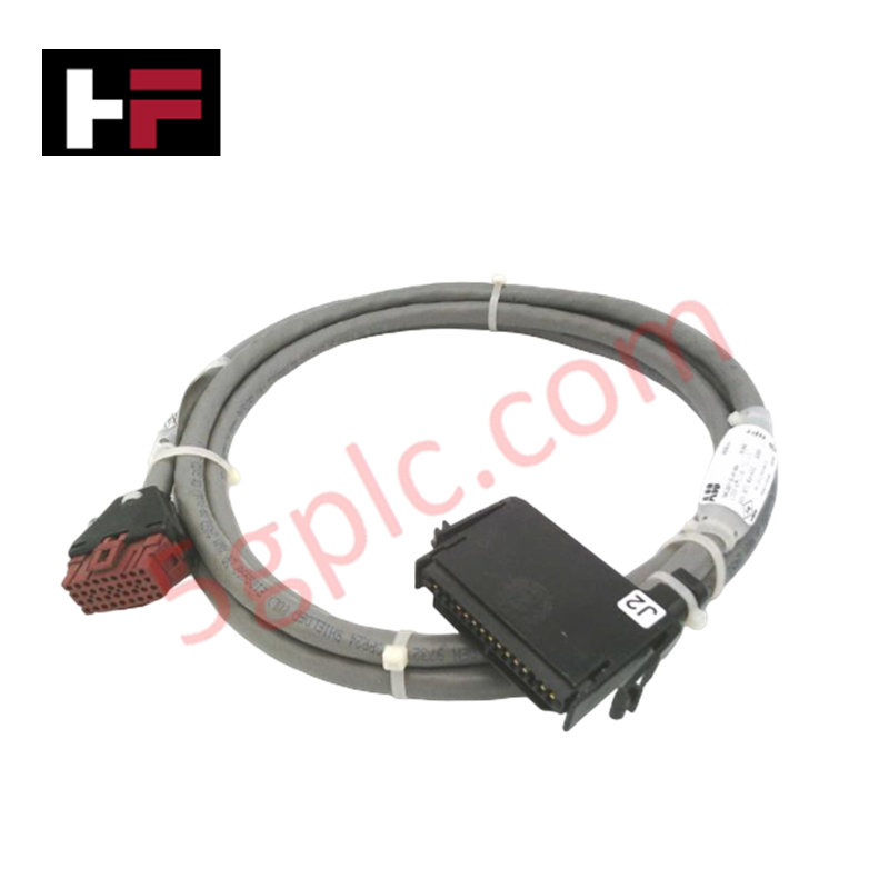

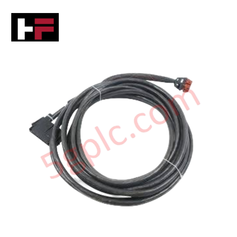
Product Details
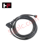
The ABB NKLM01-15, also cataloged as the NKLM01 Loop Interface Cable, operates as a dedicated hardware component for serial/data interconnection between field devices and controllers within Bailey Net 90 platforms.
Hardware Specifications
| Parameter | Specification |
|---|---|
| Model | NKLM01-15 |
| Brand | ABB |
| Origin | USA (Bailey Controls Heritage) |
| Weight | 1.10 kg (Standard baseline for 15 m assembly) |
| Dimensions | 15 meters length profile |
| Operating Temp | -20 to +70 deg C (Standard industrial parameters) |
| Power Consumption | Passive data conductor (0 W internal load) |
| Product Type | Loop Interface Cable |
| Function | Data and Signal Transmission |
| Shielding | EMI-Shielded structural matrix |
Profinet / EtherNet/IP Deterministic Networks and I/O Density Scaling
The twisted-pair layout of this 15 m loop interface cable preserves balanced wave impedance during concurrent node operations. This physical protection blocks high-frequency radiation from coupling onto the bus traces when deployed near Profinet / EtherNet/IP deterministic networks. The continuous EMI-shielding structure protects internal pulse transitions, maintaining standard backplane bus communication velocity metrics and ensuring full firmware flash compatibility between connected logic nodes. This layout prevents line reflections during complex data collection cycles, maintaining the designated I/O density scaling configuration.
Frequently Asked Questions
Q: Does the physical configuration of the NKLM01-15 loop cable permit live hot-swap insertion?
A: No. Connecting or disconnecting the loop interface cable while the Bailey Net 90 rack is active can drop termination line resistances, causing packet collisions, data frame loss, and immediate module diagnostic faults.
Q: How is the electrical grounding path for the cable shield matrix established?
A: The cable shield matrix terminates directly into the metal frame of the interface connectors. This design links the shield to the chassis ground bar of the host controller enclosure upon physical insertion.
Q: Can this 15 m assembly be sliced or linked with common serial adapters to extend its length?
A: Modifying the factory 15 meters length alters core capacitance and resistance profiles. These changes can reduce high-frequency filtering performance and induce data errors across the communication path.
Field Installation Guidelines
- Connector Engagement: Push the terminal plugs straight into the receptacle interfaces. Ensure the locking mechanisms latch fully to prevent physical dropouts under low-frequency floor vibration.
- Minimum Bend Radius: Maintain a minimum physical bend radius of 75 mm throughout the 15 meters cable run. Sharp bends alter conductor geometry and degrade the performance of the internal shield layer.
- Tray Layout Isolation: Route the loop interface cable assembly in low-voltage data communication trays. Keep it separate from parallel high-power AC lines or variable speed drive cabling to avoid inductive noise.
- Tensile Relief Clearances: Provide loose service loops at both termination points. Adequate slack protects the internal wire junctions from mechanical tension during cabinet maintenance or routine terminal access.
Additional Information
- 100% Genuine Parts: All products are original and authentic, ensuring reliable industrial performance.
- 30-Day Refund Guarantee: Return any in-stock item within 30 days in original, unopened packaging for a full refund (excluding shipping and fees).
- 12-Month Warranty: Covers defects in materials or workmanship; excludes misuse, normal wear, or unauthorized modifications.
- Worldwide Shipping: We ship via USPS, UPS, FedEx, and DHL. Delivery times vary by country and may be subject to customs or import fees.
- Support & Contact: Technical and warranty assistance is available anytime. Contact us here: Contact.
- Purchase Guidance: Check product specifications and compatibility carefully before ordering to ensure proper application.









Tech & Buying Guide

Comprehensive Guide to Noise Types in Industrial Automation and Electronics

Mitigating Emergency Stop Spurious Trips in Industrial Control Systems
Emergency stop (E-Stop) pushbuttons serve as vital safety devices in factory automation and process control plants. Functional safety standards mandate normally-closed (NC) contact blocks to ensure fail-safe operation during wiring breaks or power outages. However, mechanical degradation over time can trigger unexpected spurious trips, halting production lines without an actual emergency. Understanding the underlying causes of mechanical contact failure allows automation engineers to implement robust, fault-tolerant safety circuits.

Redundant Automation Systems: Maximizing Uptime in Critical Control Applications
Industrial automation relies on continuous operational stability to prevent catastrophic downtime and financial loss. While standard dictionary definitions treat redundancy as superfluous, industrial engineers consider redundant control architectures indispensable for high-availability systems. Implementing backup hardware ensures seamless takeover during primary equipment failures, protecting critical infrastructure across manufacturing and process industries.