










Product Details
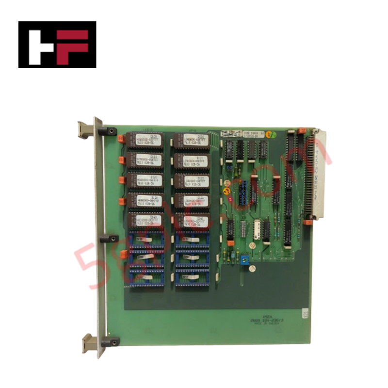
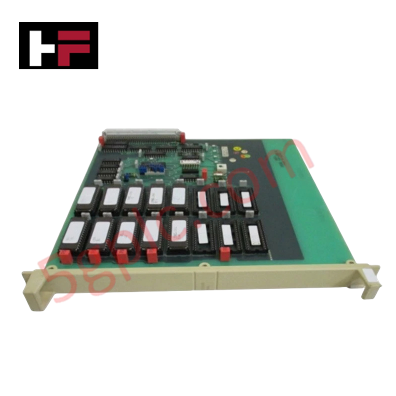
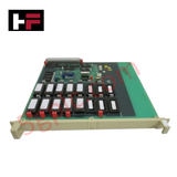
The ABB DSMB 144 57360001-EL/1, also cataloged as the DSMB 144 Memory Module, operates as a dedicated hardware component for firmware instruction storage and system memory address decoding within Advant Master process control system platforms.
Hardware Specifications
| Parameter | Specification |
|---|---|
| Model | DSMB 144 |
| Part Number | 57360001-EL/1 |
| Brand | ABB |
| Product Type | Memory Modules |
| Operating Temp | 0 to +55 deg C |
| Power Consumption | Standard Backplane Bus Draw |
| Memory Capacity | 16 x 32 KB EPROM Sockets |
| PCB Construction | Green multi-layer printed circuit board (PCB) |
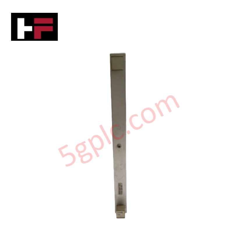
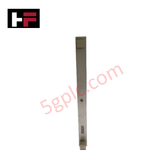
| Front Panel | Metal panel with system status indicator lights |
| System Platform | Advant Master Process Control System |
| WEEE Compliance | Not within the scope of the WEEE directive |
Backplane Bus Interface and Firmware Flash Compatibility
The board architecture integrates 16 EPROM chip sockets alongside hardware address decoding circuits, data buffering networks, and a standard DCS internal bus connector. This configuration maintains deterministic backplane bus communication velocity during system startup and bus read cycles. Integrated data buffering circuits isolate the EPROM memory array from transient bus noise, ensuring firmware flash compatibility and continuous data transfer stability across the Advant Master backplane.
Frequently Asked Questions
Q: Can EPROM chips on the DSMB144 board be hot-swapped while the rack is powered?
A: No, the DSMB144 module must be de-energized and extracted from the backplane prior to installing or removing EPROM chips to prevent electrical damage to the IC sockets and bus interface logic.
Q: What physical indicators are present on the front panel to signal operational status?
A: The front panel includes system status indicator lights mounted on a rigid metal faceplate to display board initialization and backplane communication activity.
Q: How does the module interface with the main central processing unit?
A: The board connects directly to the DCS internal backplane via a standard multi-pin bus connector, utilizing on-board address decoding and data buffering circuits to route memory calls.
Field Installation Guidelines
- Power down the controller rack segment prior to inserting or removing the DSMB144 module from the subrack frame.
- Wear a grounded wrist strap attached to chassis ground to prevent electrostatic discharge when handling the multi-layer PCB and EPROM ICs.
- Align the green PCB board edges with the subrack guide rails and slide the module smoothly until the backplane connector seats completely.
- Tighten top and bottom metal faceplate screws to establish direct chassis ground continuity and secure physical alignment.
- Verify that field signal wiring in adjacent slots maintains a minimum 200 mm physical clearance from backplane control buses to suppress induced electromagnetic interference.
Additional Information
- 100% Genuine Parts: All products are original and authentic, ensuring reliable industrial performance.
- 30-Day Refund Guarantee: Return any in-stock item within 30 days in original, unopened packaging for a full refund (excluding shipping and fees).
- 12-Month Warranty: Covers defects in materials or workmanship; excludes misuse, normal wear, or unauthorized modifications.
- Worldwide Shipping: We ship via USPS, UPS, FedEx, and DHL. Delivery times vary by country and may be subject to customs or import fees.
- Support & Contact: Technical and warranty assistance is available anytime. Contact us here: Contact.
- Purchase Guidance: Check product specifications and compatibility carefully before ordering to ensure proper application.









Tech & Buying Guide

Demystifying Open Platform Communication (OPC): The Backbone of Industrial Interoperability
Interoperability remains a cornerstone requirement for modern smart factories and process automation. Open Platform Communication (OPC) bridges the gap between disparate hardware platforms, control systems, and visualization software. By establishing a universal communication standard, OPC allows field controllers, SCADA platforms, and enterprise software from different vendors to exchange real-time data seamlessly.

Understanding Siemens PLC Memory Cards: MMC, SMC, and SD Solutions in Industrial Automation
Memory management plays a pivotal role in maintaining control system reliability across modern manufacturing plants. Industrial control systems rely on specialized memory cards to store project logic, firmware updates, and retentive system data. Siemens uses several memory architectures, including Micro Memory Cards (MMC) and SIMATIC Memory Cards (SMC). Engineers must understand these hardware variations to ensure zero data loss and minimize downtime during maintenance routines.

Redefining Control Systems: The Rise of Flexible I/O Modules in Industrial Automation
Conventional input-output architectures often limit engineering agility and inflate long-term inventory costs. Today, Flexible Input/Output Modules (FIOM) are transforming how control system engineers design, commission, and maintain automation infrastructure. By allowing individual channel software configuration, FIOM technology bridges the gap between rigid hardware design and dynamic plant requirements.