










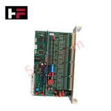
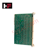
Product Details
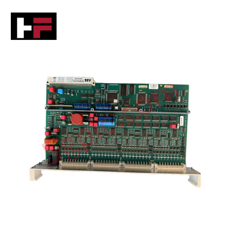
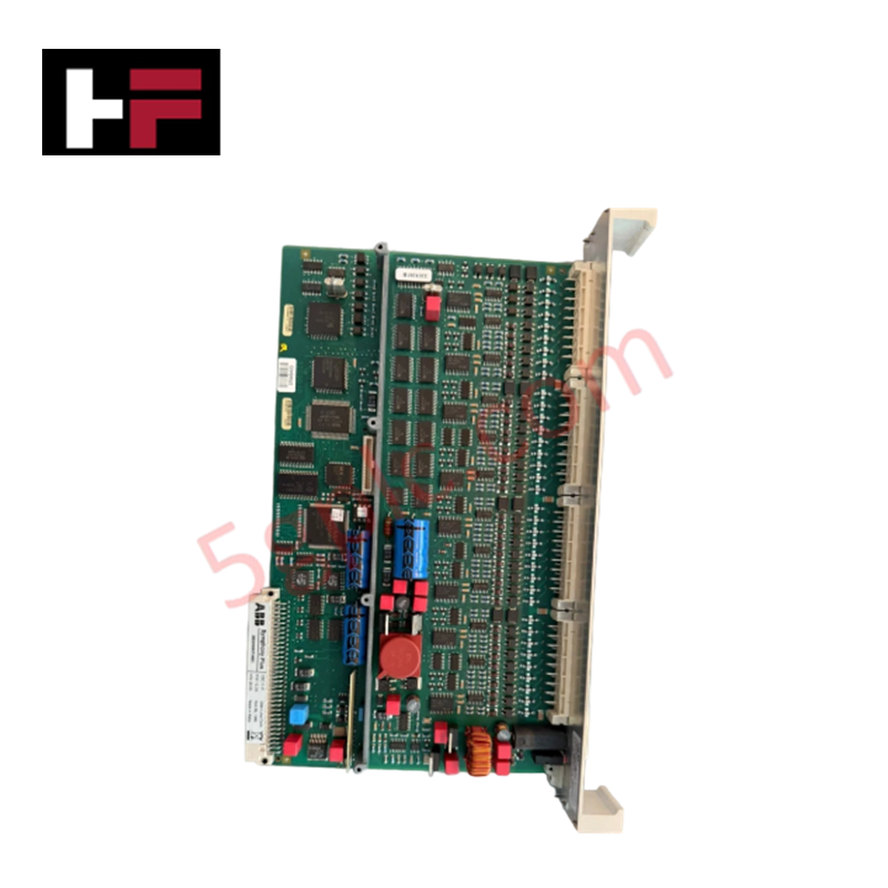
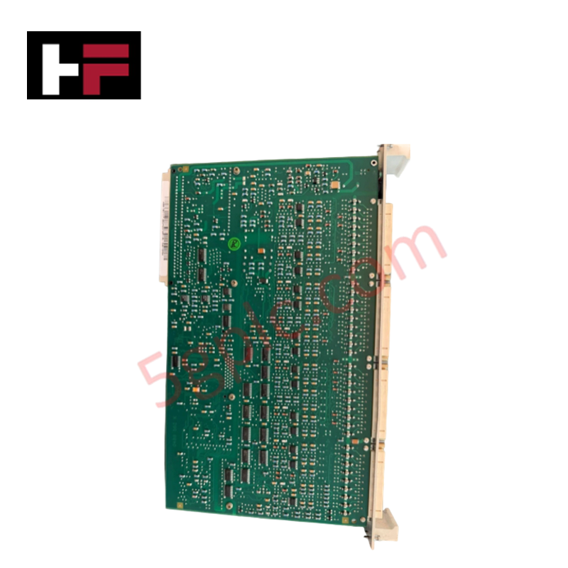
The ABB CBC 11-P 3BDH000734R1, also cataloged as the CBC 11-P Open Loop Control Module, operates as a dedicated hardware component for multi-channel discrete and actuation signal processing within ABB automation control systems. Running software version 1.31 or higher, the unit controls coupling relays, transmitter power supplies, motor drives, and solenoid actuators across 48 input channels and 36 output channels.
Hardware Specifications
| Parameter | Specification |
|---|---|
| Model | CBC 11-P (3BDH000734R1) |
| Brand | ABB |
| Origin | Germany |
| Product Type | Open Loop Control Modules |
| Firmware/Software Version | SW Version 1.31 or higher |
| Channel Configuration | 48 Input Channels / 36 Output Channels (DX Channel Type) |
| Channel Structure | 7 / 14 Channels with galvanic isolation per group |
| Supported Applications | Coupling Relay-Control, Transmitter Power Supply, Motor Drive, Solenoid Actuator |
| Required Accessories | 4 pcs CI 100/101, Cable Clamp |
| Dimensions (W x H x D) | 45 mm x 340 mm x 204 mm |
| Net Weight | 0.69 kg |
| Operating Temp | 0 to +55 deg C |
| Power Consumption | System backplane and external field loop supply dependent |
| Environmental Compliance | Following EU Directive 2011/65/EU (RoHS) |
Channel-to-Channel Isolation and Deterministic Network Execution
The module implements group-based galvanic isolation across its 7 / 14 channel sections to prevent field ground loops and voltage transients from propagating into system electronics. Backplane communication interfaces operate with deterministic timing to deliver high-density channel state updates directly to controller processors. Firmware flash compatibility ensures that system configuration matrices, group channel mappings, and logic parameters remain stable during system reboot cycles or field bus disruptions.
Frequently Asked Questions
Q: What mandatory accessories are required to deploy the CBC 11-P module?
A: The module requires four CI 100/101 units and matching cable clamps to secure interface connections and strain relief.
Q: How is galvanic isolation structured across the I/O channels?
A: The channels feature group-level galvanic isolation arranged in 7 / 14 channel blocks, protecting internal module logic from field-side voltage fluctuations.
Field Installation Guidelines
- Power De-energization: Verify that all internal system bus power and external field loop power supplies are de-energized prior to inserting or removing the module.
- Slot Mechanical Insertion: Align the module circuit board edges with the enclosure slot guides. Slide the module in firmly until the backplane connectors seat completely, then fasten all mechanical retention hardware.
- Accessory and Cable Strain Relief: Mount the mandatory CI 100/101 accessories and secure all field signal cables using the provided cable clamps to prevent mechanical strain on terminal pins.
- Shield Grounding: Terminate all signal wiring drain wires to the panel earth bus bar via low-impedance grounding connections. Maintain clear physical separation between AC power wiring and DC/analog signal cabling within wire ducts.
Additional Information
- 100% Genuine Parts: All products are original and authentic, ensuring reliable industrial performance.
- 30-Day Refund Guarantee: Return any in-stock item within 30 days in original, unopened packaging for a full refund (excluding shipping and fees).
- 12-Month Warranty: Covers defects in materials or workmanship; excludes misuse, normal wear, or unauthorized modifications.
- Worldwide Shipping: We ship via USPS, UPS, FedEx, and DHL. Delivery times vary by country and may be subject to customs or import fees.
- Support & Contact: Technical and warranty assistance is available anytime. Contact us here: Contact.
- Purchase Guidance: Check product specifications and compatibility carefully before ordering to ensure proper application.









Tech & Buying Guide

Static UPS vs. Rotary UPS: Technical Evaluation for Industrial Automation

Comprehensive Guide to Noise Types in Industrial Automation and Electronics

Mitigating Emergency Stop Spurious Trips in Industrial Control Systems
Emergency stop (E-Stop) pushbuttons serve as vital safety devices in factory automation and process control plants. Functional safety standards mandate normally-closed (NC) contact blocks to ensure fail-safe operation during wiring breaks or power outages. However, mechanical degradation over time can trigger unexpected spurious trips, halting production lines without an actual emergency. Understanding the underlying causes of mechanical contact failure allows automation engineers to implement robust, fault-tolerant safety circuits.