










Product Details
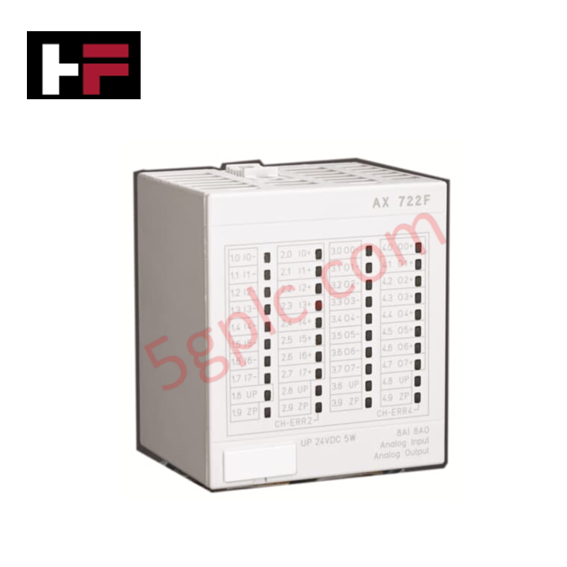
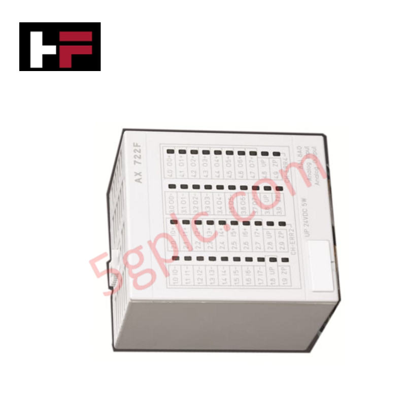
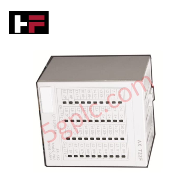
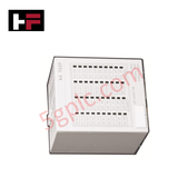
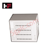
The ABB AX 722F 3BDH000377R0005, also cataloged as the AX 722F Analog Input/Output Module, operates as a dedicated hardware component for multi-channel analog signal acquisition and control output generation within Freelance S700 I/O system platforms. Equipped with 16 non-redundant channels housing 12-bit analog input and configurable analog output circuits, the module supports voltage ranges from -10 to +10 V, current ranges up to 0 to 20 mA/4 to 20 mA, and temperature sensing resolutions of 0.1 deg C (0.18 deg F). Operating with an external 24 VDC current draw of 0.10 A and a maximum power dissipation of 6 W, the 300 g unit provides real-time channel diagnostics through 40 front-panel status LEDs over field cable distances up to 100 m.
Hardware Specifications
| Parameter | Specification |
|---|---|
| Model | AX 722F (3BDH000377R0005) |
| Base Model | AX 722F |
| Brand | ABB |
| Origin | Sweden |
| Weight | 300 g |
| Dimensions | 67.5 mm x 54 mm x 76 mm (W x H x D) |
| Operating Temp | -20 deg C to +60 deg C |
| Power Consumption | 6 W max power dissipation (0.10 A at 24 VDC external) |
| Number of Channels | 16 channels |
| Analog Resolution | Input: 12 bits (+ sign); Output: 12 bits (0-10 V, 0-20 mA, 4-20 mA) / 12 bits + sign (-10 to +10 V); Temp: 0.1 deg C / 0.18 deg F |
| Input Voltage Range "0" | -30 V to +5 V |
| Input Voltage Range "1" | +13 V to +30 V |
| Common Mode Voltage | 24 VDC |
| Max Field Cable Length | 100 m |
| Mechanical Form Factor | S700 module housing |
| Status Diagnostics | 40 front LEDs for signal intensity and error indication |
Backplane Bus Communication Velocity and Firmware Flash Compatibility
Interfacing directly with the S700 local bus structure, the module delivers steady data update rates that match controller backplane bus communication velocity across distributed process networks. Direct integration of mixed input and output circuitry allows flexible I/O density scaling inside compact junction enclosures, reducing overall panel space requirements. Controller firmware flash compatibility enables dynamic parameter downloads for channel scale conversion, signal clamping limits, and sensor linearizations without interrupting background system diagnostic loops.
Frequently Asked Questions
Q: How do the front-panel status LEDs indicate changing signal levels across active channels?
A: The brightness of each individual channel LED dynamically varies proportionally to the loop current intensity or measured voltage amplitude.
Q: What are the primary cable distance limits for field instrumentation attached to this module?
A: Field wiring runs connected to signal terminals must not exceed a maximum distance of 100 m to ensure rated measurement accuracy and signal integrity.
Field Installation Guidelines
- Mount the module securely onto the designated S700 terminal base unit until both mechanical retention latches click into place.
- Maintain complete physical isolation between low-level analog wiring and high-voltage AC power lines within the enclosure wire ducts.
- Connect all field shield drain wires to the central enclosure ground rail at the cabinet entrance point to mitigate common-mode electrical noise.
- Verify external 24 VDC auxiliary power connections before applying system power to ensure proper initial initialization of module diagnostics.
Additional Information
- 100% Genuine Parts: All products are original and authentic, ensuring reliable industrial performance.
- 30-Day Refund Guarantee: Return any in-stock item within 30 days in original, unopened packaging for a full refund (excluding shipping and fees).
- 12-Month Warranty: Covers defects in materials or workmanship; excludes misuse, normal wear, or unauthorized modifications.
- Worldwide Shipping: We ship via USPS, UPS, FedEx, and DHL. Delivery times vary by country and may be subject to customs or import fees.
- Support & Contact: Technical and warranty assistance is available anytime. Contact us here: Contact.
- Purchase Guidance: Check product specifications and compatibility carefully before ordering to ensure proper application.









Tech & Buying Guide

Demystifying the DDE Protocol in Legacy Industrial Automation Systems
Modern control systems rely heavily on seamless interprocess communication to exchange operational data between software programs. Microsoft first introduced the Dynamic Data Exchange (DDE) protocol in 1987 to enable real-time data sharing. In factory automation, DDE served as an early bridge between control software and Windows desktop applications. Therefore, understanding DDE mechanics provides crucial insights into how legacy industrial networks established software-level connectivity.

Demystifying CPU Communication Ports in Siemens PLC Architectures
Industrial automation relies heavily on robust data exchange between devices. Without seamless connectivity, field instruments, network switches, human-machine interfaces, and programmable logic controllers cannot coordinate effectively. Therefore, understanding the various CPU communication ports available in Siemens hardware ensures efficient factory automation design and seamless system integration.

Mastering the Siemens PLC Scan Cycle: How the CPU Executes Automation Programs
Industrial automation relies heavily on programmable logic controllers (PLCs) to manage complex manufacturing processes. Many engineers dive straight into programming without mastering the underlying architecture. However, understanding how a PLC CPU executes a program ensures reliable system design. Therefore, mastering the scan cycle optimizes both performance and troubleshooting in modern control systems.