










Product Details
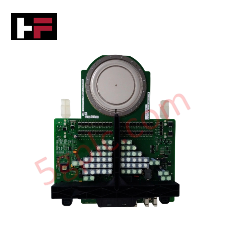
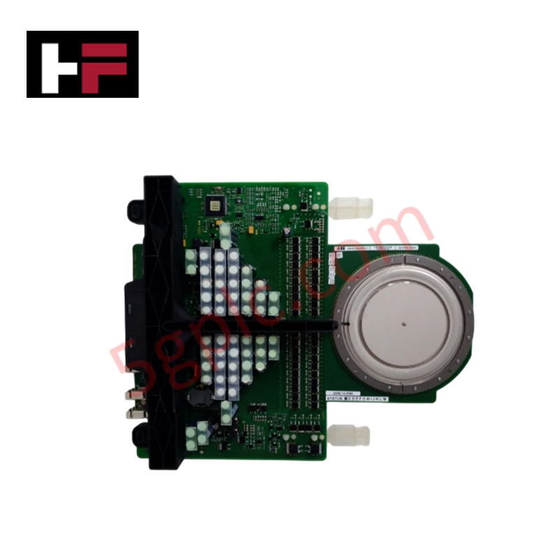
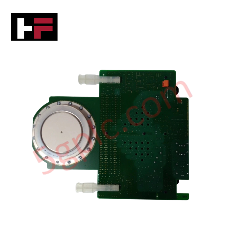
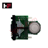
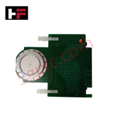
The ABB 3BHE009681R0101, also cataloged as the 3BHE009681R0101 Integrated Gate-Commutated Thyristor (IGCT) Module, operates as a dedicated hardware component for high-power solid-state circuit commutation within multi-phase variable frequency drives and static VAR compensators. The assembly integrates the 3BHB013088R0001 gate unit and the 5SHY3545L0010 thyristor to execute fast electrical switching sequences directly inside high-voltage transmission and power conversion systems.
Hardware Specifications
| Parameter | Specification |
|---|---|
| Model | 3BHE009681R0101 |
| Brand | ABB |
| Sub-Assembly Models | 3BHB013088R0001 / 5SHY3545L0010 |
| Origin | Sweden |
| Nominal Voltage | 4500 V |
| Nominal Current | 3500 A |
| Peak Gate Current (Turn-On/Off) | 1000 A |
| Turn-On / Turn-Off Time | 1.5 us / 1.5 us |
| On-State Voltage Drop | 2.5 V |
| Off-State Leakage Current | 10 mA |
| Maximum Junction Temperature | 125 deg C |
| Dimensions | 320 mm x 200 mm x 150 mm |
| Weight | 1.5 kg |
| Operating Temp | Dependent on configuration (Junction limit up to 125 deg C) |
| Power Consumption | Determined by operational switching frequency |
Profinet and EtherNet/IP Deterministic Networks Execution
The command timing logic inside this hardware must map synchronously to the network cycle times of the host controller. To maintain sub-microsecond pulse precision during a 3500 A conduction phase, the device relies on precise I/O density scaling and internal backplane processing. Matching the gate driver firmware flash compatibility with the supervisory drive control network is required to avoid gating delays. This synchronization ensures that commands transmitted via deterministic fieldbuses are executed immediately by the integrated gate drive, eliminating phase shifting within the output inverter bridge.
Frequently Asked Questions
Q: What are the live removal or hot-swap restrictions for this IGCT assembly?
A: This module has zero hot-swap capabilities. Attempting extraction or insertion while the main 4500 V DC link or the auxiliary gate control power is energized will result in catastrophic failure of the semiconductor substrate and arc flash hazards.
Q: How does firmware versioning affect the operation of the embedded 3BHB013088R0001 gate board?
A: The embedded gate board functions with dedicated, factory-flashed logic configurations. Firmware parameters must explicitly match the modulation frequency limits of the main controller card to prevent exceeding the 1.5 us commutation limits.
Q: What power source is required to drive the 1000 A peak turn-on gate current?
A: The peak gating currents are supplied by internal storage capacitors on the 3BHB013088R0001 gate unit board, which requires an isolated steady-state auxiliary DC power feed from the drive cabinet distribution rail.
Field Installation Guidelines
- Clamping Pressure and Mechanical Alignment: Mount the module within a calibrated semiconductor press frame. Apply the exact factory-specified clamping force to achieve uniform pressure across the 5SHY3545L0010 element to prevent elevated on-state voltage drops.
- Control and Optical Fiber Routing: Route all high-voltage gating power and fiber-optic signal connections through dedicated, isolated conduits. Separate these links from high-power phase bars to prevent inductive cross-talk.
- Thermal Sink Preparation: Thoroughly clean all contact faces on the copper or aluminum cooling blocks. Apply a thin layer of specialized thermal paste to maximize heat dissipation from the base plate to the thermal dissipation matrix.
Additional Information
- 100% Genuine Parts: All products are original and authentic, ensuring reliable industrial performance.
- 30-Day Refund Guarantee: Return any in-stock item within 30 days in original, unopened packaging for a full refund (excluding shipping and fees).
- 12-Month Warranty: Covers defects in materials or workmanship; excludes misuse, normal wear, or unauthorized modifications.
- Worldwide Shipping: We ship via USPS, UPS, FedEx, and DHL. Delivery times vary by country and may be subject to customs or import fees.
- Support & Contact: Technical and warranty assistance is available anytime. Contact us here: Contact.
- Purchase Guidance: Check product specifications and compatibility carefully before ordering to ensure proper application.









Tech & Buying Guide

Demystifying CPU Communication Ports in Siemens PLC Architectures
Industrial automation relies heavily on robust data exchange between devices. Without seamless connectivity, field instruments, network switches, human-machine interfaces, and programmable logic controllers cannot coordinate effectively. Therefore, understanding the various CPU communication ports available in Siemens hardware ensures efficient factory automation design and seamless system integration.

Mastering the Siemens PLC Scan Cycle: How the CPU Executes Automation Programs
Industrial automation relies heavily on programmable logic controllers (PLCs) to manage complex manufacturing processes. Many engineers dive straight into programming without mastering the underlying architecture. However, understanding how a PLC CPU executes a program ensures reliable system design. Therefore, mastering the scan cycle optimizes both performance and troubleshooting in modern control systems.

How to Connect to Siemens S7 PLCs: 5 Essential Communication Methods
Establishing a reliable hardware link between a programming terminal and a Siemens SIMATIC controller is essential for engineering workflows. Field engineers rely on distinct physical layers, ranging from legacy serial connections to high-speed Industrial Ethernet protocols. Modern factory automation environments prioritize fast data transfer and seamless driver integration. Selecting the correct connection method simplifies program downloads, online monitoring, and system troubleshooting in complex control systems.