








Product Details
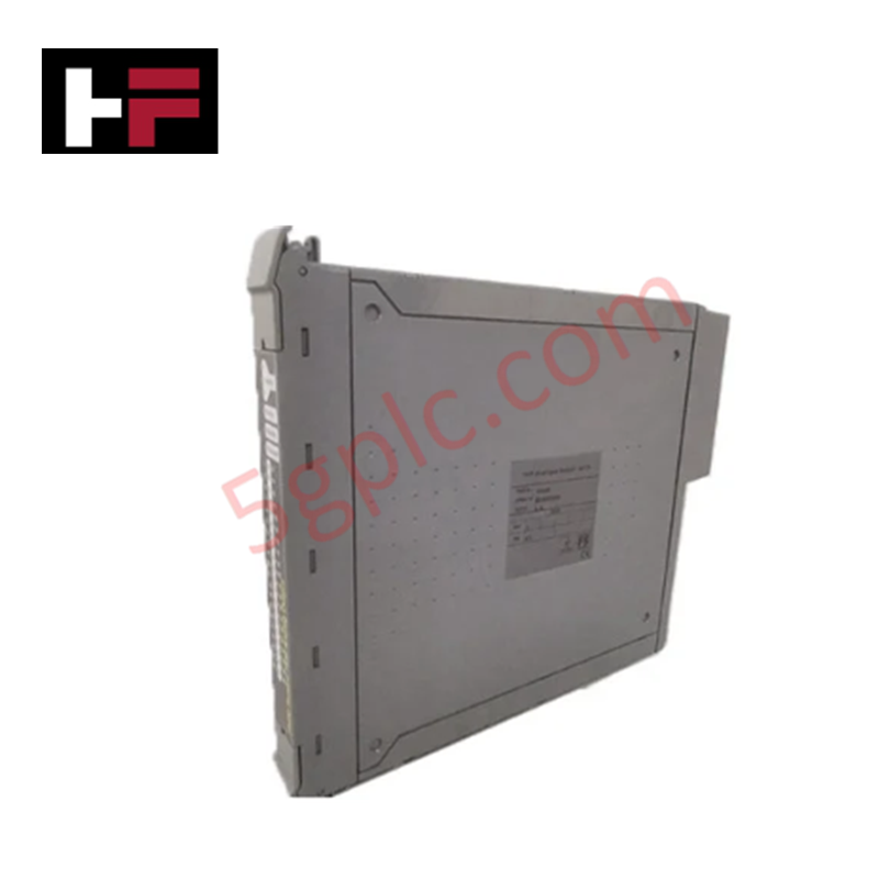
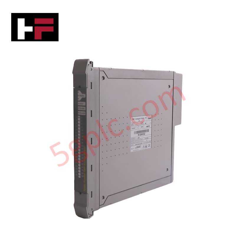
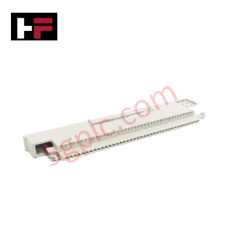
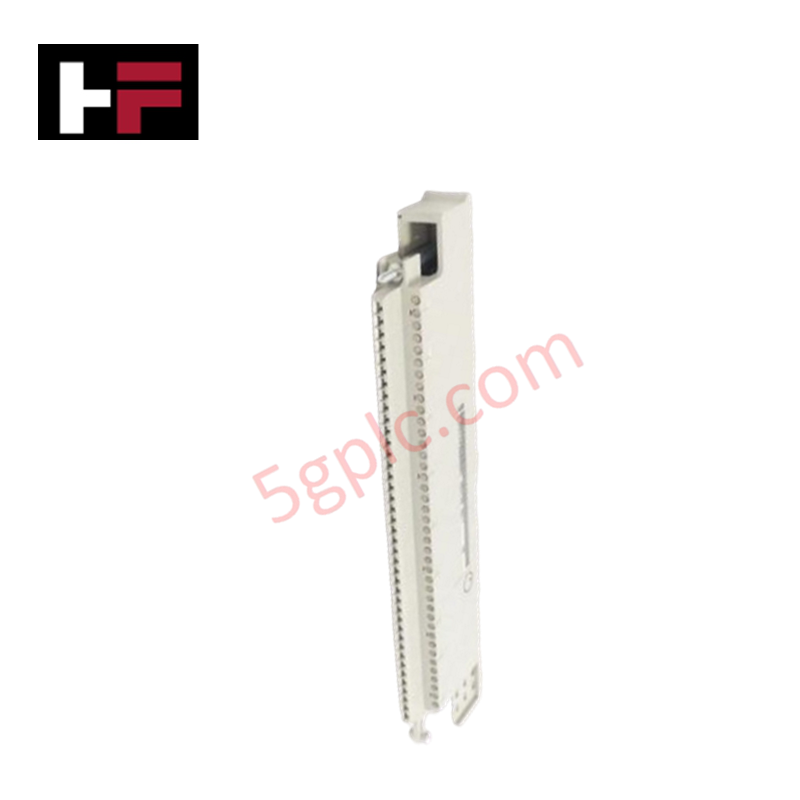
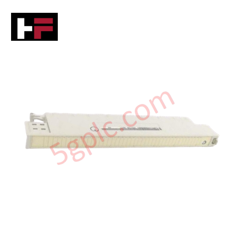
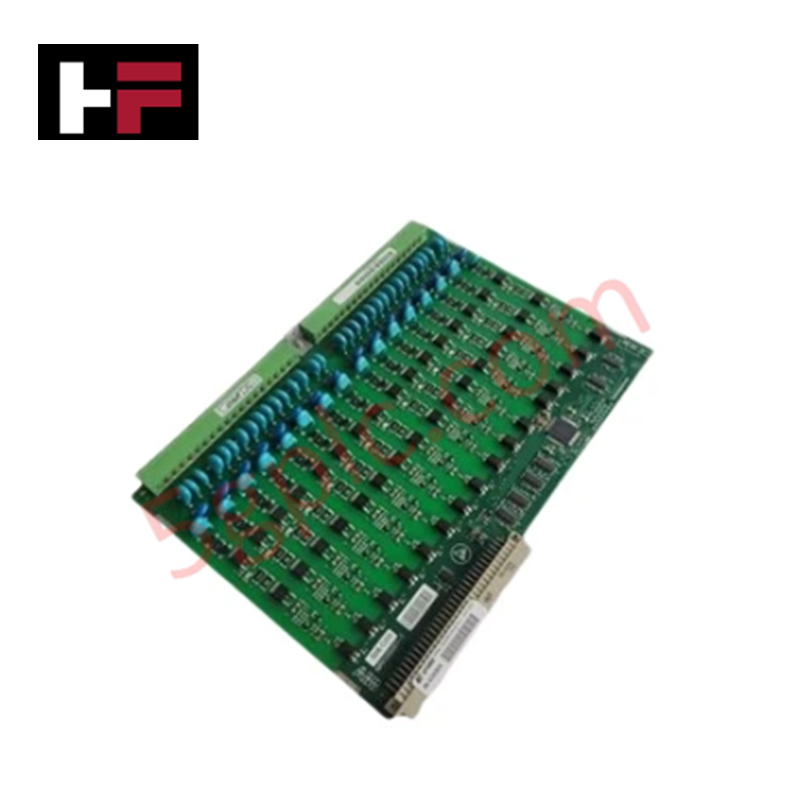
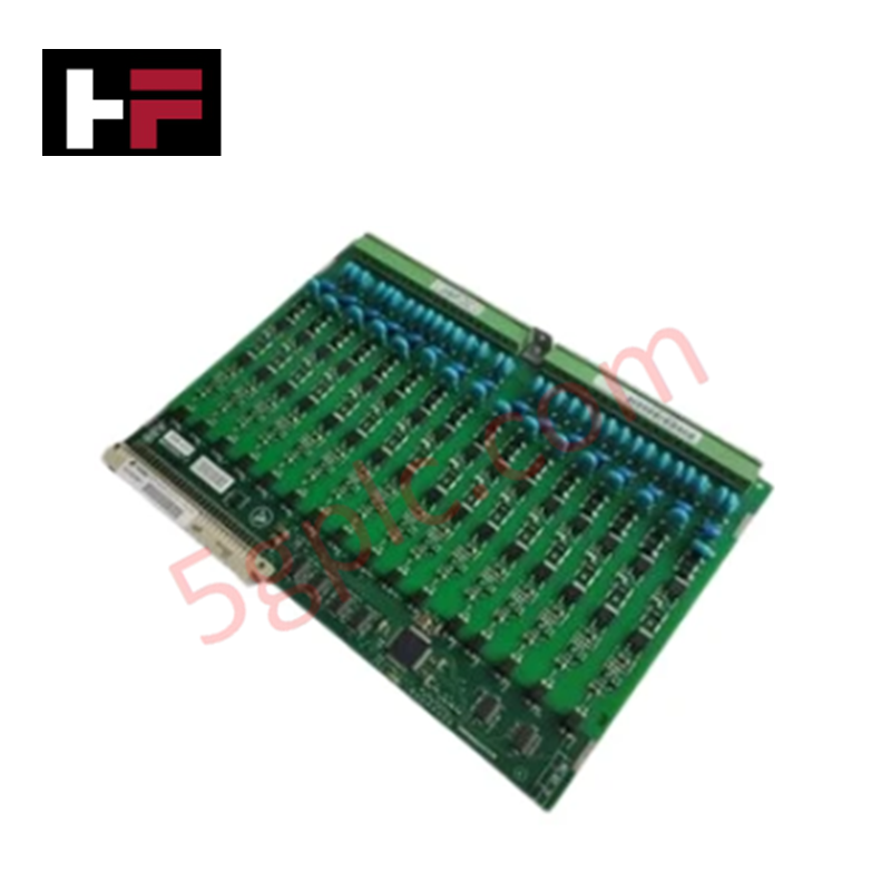
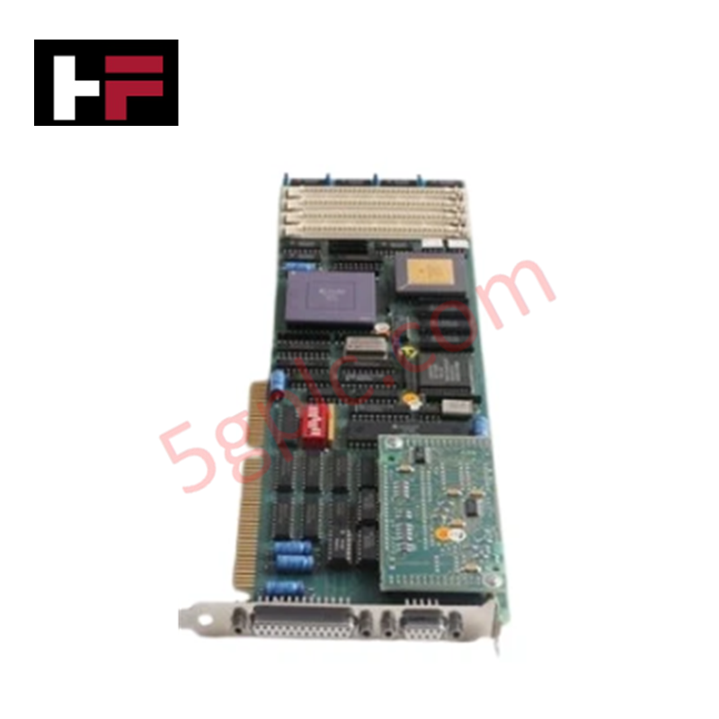
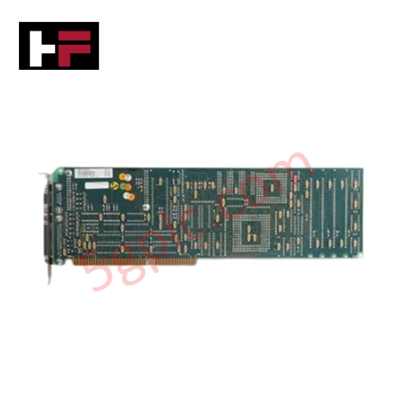
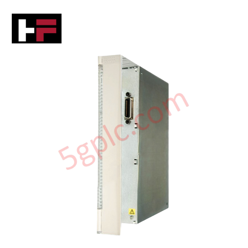
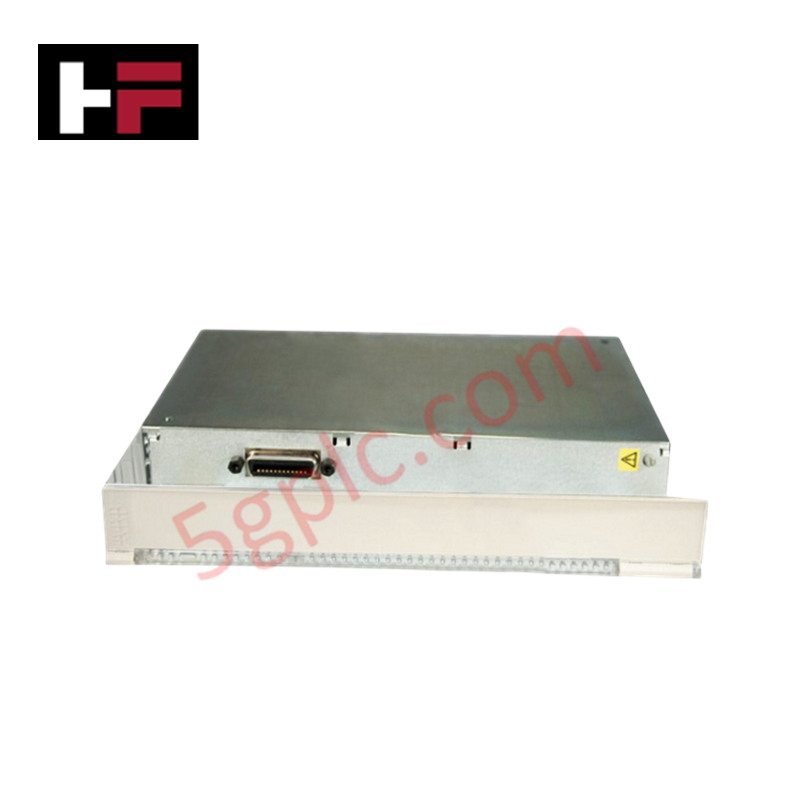
The ABB 35ST90 GJR5144900R0001, also cataloged as the 35ST90 Front Connector Module, operates as a dedicated hardware component for field signal termination and wiring interface consolidation within ABB Symphony, Master, and Freelance DCS platforms. Constructed from corrosion-resistant brass alloy with an IP67 M12 connector type, it routes up to 16 discrete or analog channels across a wire gauge range of 0.14 mm2 to 1.0 mm2. The assembly operates at a rated current of 10 A and voltages up to 100 V DC across ambient operating temperatures from -40 deg C to +70 deg C.
Hardware Specifications
| Parameter | Specification |
|---|---|
| Model | 35ST90 (GJR5144900R0001) |
| Base Model | 35ST90 |
| Brand | ABB |
| Origin | Sweden |
| Weight | 0.45 kg |
| Dimensions | 35 x 90 x 50 mm |
| Operating Temp | -40 deg C to +70 deg C |
| Power Consumption | Passive Component / 10 A Current Limit |
| Material | Corrosion-resistant Brass Alloy |
| Connector Type | M12, IP67 rated |
| Connection Count | 16-pin |
| Operating Voltage | Up to 100 V DC |
| Wire Gauge | 0.14 mm2 - 1.0 mm2 |
| System Compatibility | ABB Symphony, Master, Freelance DCS |
Backplane Bus Communication Velocity and Density Scaling
The passive physical interconnection design preserves high backplane bus communication velocity and signal integrity when scaling I/O density on active rack cards. Contact resistance across all 16 pins is minimized to eliminate signal distortion during high-frequency data sampling. Direct terminal engagement ensures full electrical compatibility across system processor flash firmware updates without requiring modifications to field terminal wiring.
Frequently Asked Questions
Q: What are the maximum wire gauge and current limits per terminal pin?
A: The connector accepts conductor cross-sections between 0.14 mm2 and 1.0 mm2 (26 AWG to 18 AWG) and supports a maximum current rating of 10 A per pin at up to 100 V DC.
Q: How is the IP67 ingress protection rating maintained at the field interface?
A: IP67 protection requires fully tightening the M12 screw coupling until seated against the integral rubber gasket, preventing dust and water entry into the 16-pin contact array.
Field Installation Guidelines
- Strip field conductors to 6-8 mm, ensuring individual wire strands are fully inserted into terminal clamping points without stray conductors.
- Align the 16-pin guide key with the mating I/O module faceplate before pressing the connector into place.
- Hand-tighten the M12 metallic coupling ring to lock the connector body onto the card frame and ensure grounding continuity.
- Route field wiring through strain-relief channels inside the control cabinet to avoid mechanical tension on the screw terminals.
Additional Information
- 100% Genuine Parts: All products are original and authentic, ensuring reliable industrial performance.
- 30-Day Refund Guarantee: Return any in-stock item within 30 days in original, unopened packaging for a full refund (excluding shipping and fees).
- 12-Month Warranty: Covers defects in materials or workmanship; excludes misuse, normal wear, or unauthorized modifications.
- Worldwide Shipping: We ship via USPS, UPS, FedEx, and DHL. Delivery times vary by country and may be subject to customs or import fees.
- Support & Contact: Technical and warranty assistance is available anytime. Contact us here: Contact.
- Purchase Guidance: Check product specifications and compatibility carefully before ordering to ensure proper application.
Tech & Buying Guide

Preventing Emergency Stop Spurious Trips in Industrial Control Systems
Emergency Stop pushbuttons use Normally Closed contacts for fail-safe safety, but mechanical wear can cause costly spurious trips. This technical guide examines E-Stop contact failure root causes, redundant hardware setups, PLC logic monitoring, and maintenance strategies to maximize plant availability.

Why 24V DC Is the Universal Standard for Industrial Automation Power Supplies
Industrial manufacturing requires continuous uptime to prevent equipment damage. Unlike AC power, 24V DC circuits seamlessly integrate with UPS units and battery banks. During main grid failures, a 24V DC backup system instantly maintains PLC memory, instrument loops, and critical safety valves without interruption.

Site Acceptance Testing (SAT) for PLC Control Systems: An Engineering Execution Guide
The Site Acceptance Test (SAT) represents the definitive handover stage in industrial automation projects. While the Factory Acceptance Test confirms cabinet hardware assembly off-site, the SAT validates real-world performance under live site conditions. Consequently, a structured execution strategy prevents equipment damage and guarantees seamless integration into plant operations.