










Product Details
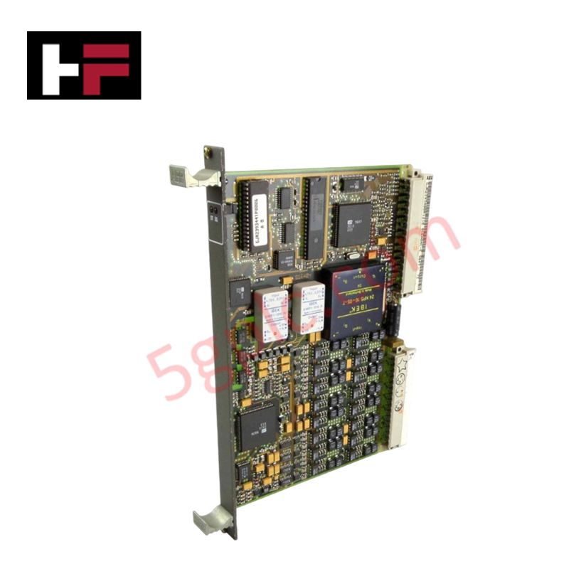
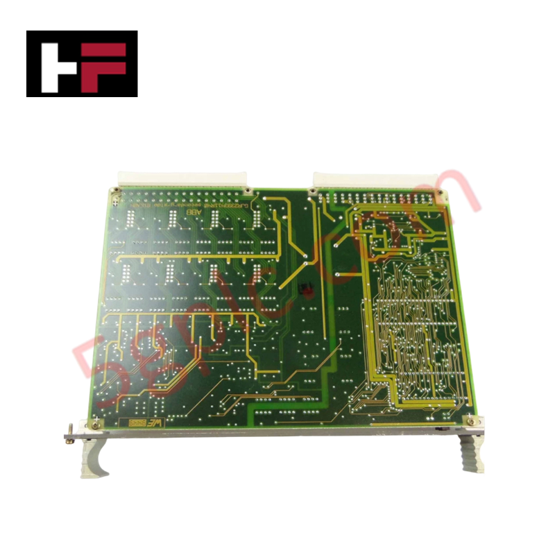
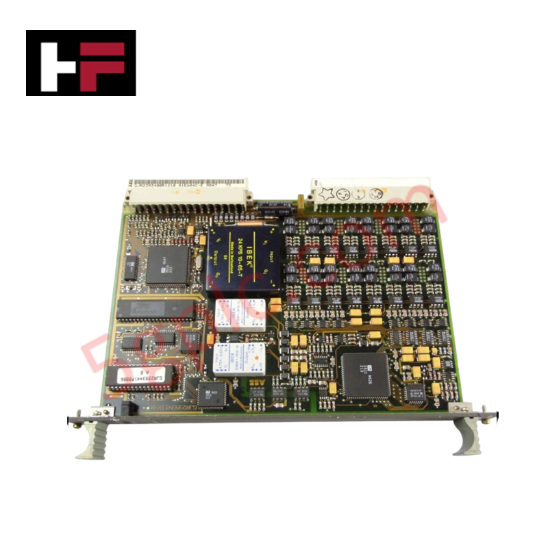
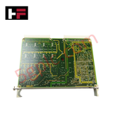
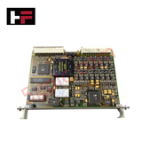
Configured for multi-range current signal processing in legacy Procontic or Advant master architectures, the ABB 81EA04C-E GJR2393400R1210 (81EA04C-E Analog Input Module) provides direct physical/electrical execution. The 16-channel potential-independent subsystem samples low-level current loops, executing high-resolution analog-to-digital conversions to present processed process variables directly to the host processing unit.
Hardware Specifications
| Parameter | Specification |
|---|---|
| Model | 81EA04C-E |
| Part Number | GJR2393400R1210 |
| Brand | ABB |
| Origin | Germany |
| Weight | 0.5 kg |
| Dimensions | 20 mm x 261 mm x 198 mm |
| Operating Temp | Standard industrial operating range |
| Power Consumption | Nominal backplane internal bus current draw |
| Channel Count | 16 potential-independent channels |
| Signal Input Ranges | 0 to 5 mA, 0 to 20 mA, 4 to 20 mA, 0 to 50 mA |
| Device Classification | Analog Input Module (AI) |
I/O Density Scaling and Deterministic Integration
The 81EA04C-E manages a dense 16-channel matrix of potential-independent inputs without compromising localized backplane bus communication velocity parameters. The localized digital filtering and conditioning loop logic updates measurement registers synchronously with adjacent modules. Full firmware flash compatibility enables integration into networks bridged with Profinet / EtherNet/IP deterministic protocols, allowing the subsystem to scale within expanded chassis configurations without introducing data jitter or latency into critical control routines.
Frequently Asked Questions
Q: Does the potential-independent design of the 81EA04C-E support live hot-swapping during chassis operation?
A: No. The internal backplane bus interface lacks dynamic current-limiting switches. High-voltage transients or logic bus corruption can occur if the module is extracted or inserted while the rack assembly remains energized.
Q: How are different signal ranges, such as 4-20 mA versus 0-50 mA, allocated across channels?
A: Signal range adjustments are configured through internal board-level jumpers or defined within the master system software configuration tool, allowing independent signal range mapping per channel array.
Field Installation Guidelines
- Chassis Card Mating: Slide the 20 mm wide module smoothly into the designated subrack guide rails until the rear multi-pin connector fully seats into the carrier backplane.
- Shield Grounding Matrix: Terminate all incoming analog twisted-pair instrumentation shields to a low-impedance centralized copper earth bar to isolate signal loops from stray high-frequency noise.
- Conduit Routing Restrictions: Maintain physical separation between analog input signaling cables and high-power AC/DC drive lines to minimize electromagnetic cross-talk.
Additional Information
- 100% Genuine Parts: All products are original and authentic, ensuring reliable industrial performance.
- 30-Day Refund Guarantee: Return any in-stock item within 30 days in original, unopened packaging for a full refund (excluding shipping and fees).
- 12-Month Warranty: Covers defects in materials or workmanship; excludes misuse, normal wear, or unauthorized modifications.
- Worldwide Shipping: We ship via USPS, UPS, FedEx, and DHL. Delivery times vary by country and may be subject to customs or import fees.
- Support & Contact: Technical and warranty assistance is available anytime. Contact us here: Contact.
- Purchase Guidance: Check product specifications and compatibility carefully before ordering to ensure proper application.









Tech & Buying Guide

Static UPS vs. Rotary UPS: Technical Evaluation for Industrial Automation

Comprehensive Guide to Noise Types in Industrial Automation and Electronics

Mitigating Emergency Stop Spurious Trips in Industrial Control Systems
Emergency stop (E-Stop) pushbuttons serve as vital safety devices in factory automation and process control plants. Functional safety standards mandate normally-closed (NC) contact blocks to ensure fail-safe operation during wiring breaks or power outages. However, mechanical degradation over time can trigger unexpected spurious trips, halting production lines without an actual emergency. Understanding the underlying causes of mechanical contact failure allows automation engineers to implement robust, fault-tolerant safety circuits.