


Product Details
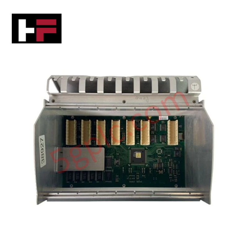
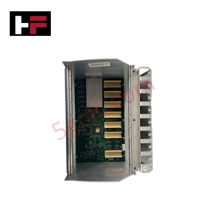
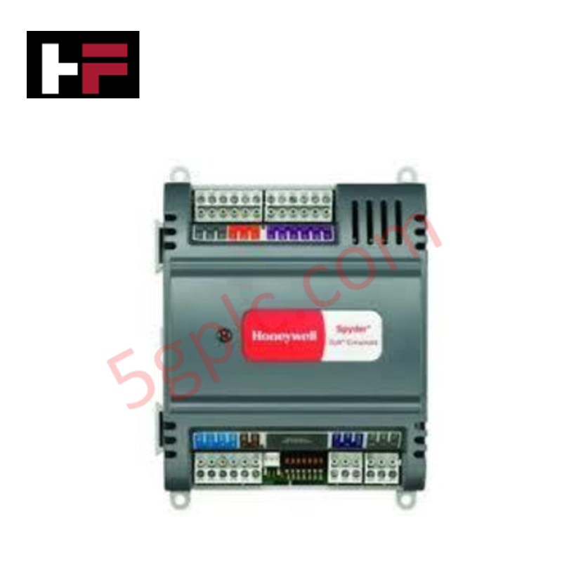
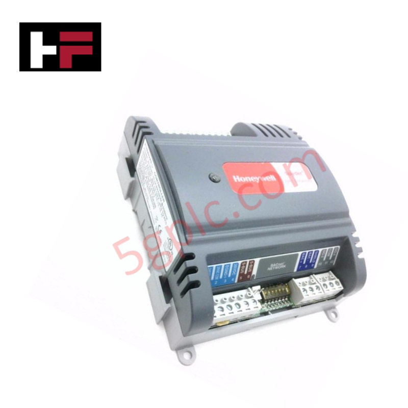
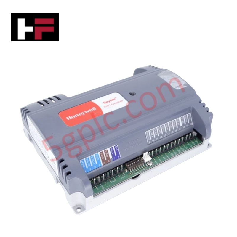
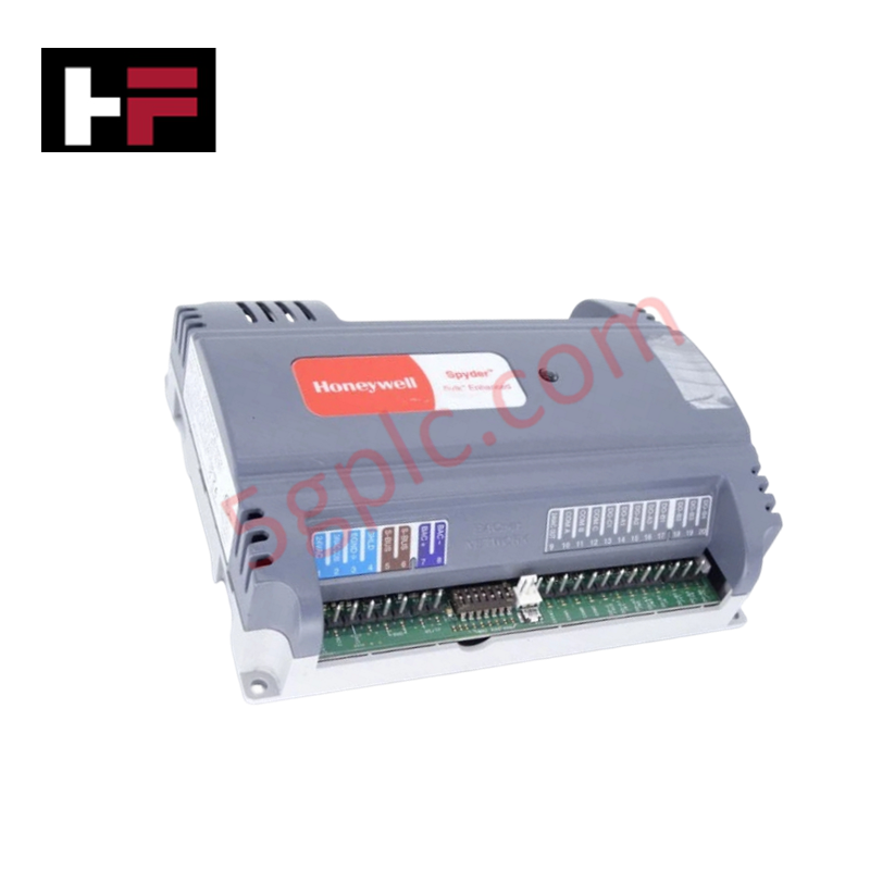
Configured for discrete logic execution in IPC 620 control platforms, the Honeywell 620-1633 (620-1633 Control Processor Module) provides direct electrical execution of user-programmed control logic. The hardware manages system I/O scanning and communication tasks via integrated physical interfaces, including 9-pin and 25-pin Sub-D connectors, while providing real-time status feedback through front-panel LED indicators and a key-operated security mode switch.
Hardware Specifications
| Parameter | Specification |
|---|---|
| Model | 620-1633 |
| Brand | Honeywell |
| Origin | Not Specified |
| Weight | 0.74 kg |
| Communication Ports | 1 x 9-pin Sub-D, 1 x 25-pin Sub-D |
| Configuration | Key-operated mode switch |
Channel-to-Channel Isolation and Loop Integrity
The 620-1633 utilizes rigorous channel-to-channel isolation on its communication ports to prevent ground loops and common-mode noise propagation between the controller and external programming or monitoring devices. This architectural separation ensures that high-speed backplane bus communication remains deterministic and resistant to electrical transients originating from peripheral hardware. Strict adherence to port-specific shielding protocols is required to maintain signal integrity and prevent EMI-induced data corruption on the communication serial interfaces.
Frequently Asked Questions
Q: Does the 620-1633 support hot-swapping while the rack backplane is energized?
A: No. The 620-1633 does not support hot-swapping. The host rack must be de-energized to prevent electrical arcing on the backplane interface and to avoid potential corruption of the processor's memory or I/O registers during module insertion.
Q: What is the function of the key-operated switch on the front panel?
A: The key-operated switch serves as a physical security lock to prevent unauthorized changes to the processor's operating mode, such as transitioning between RUN, PROGRAM, and REMOTE modes during active system operation.
Field Installation Guidelines
- System Power Isolation: Isolate all power supplies to the controller rack before installing the module to ensure no latent current exists on the backplane connector pins.
- Backplane Engagement: Slide the module into the designated processor slot. Verify that the rear edge connector is fully seated to ensure reliable communication with the I/O bus and power distribution rails.
- Cabling and Grounding: Utilize properly shielded cables for the 9-pin and 25-pin Sub-D ports. Terminate cable shields to the system's designated earth ground point to protect against transient voltage surges.
- Environment: Ensure the controller rack is installed in an environment free of excessive conductive dust or moisture, maintaining airflow to the module front panel for proper thermal dissipation of internal components.
Additional Information
- 100% Genuine Parts: All products are original and authentic, ensuring reliable industrial performance.
- 30-Day Refund Guarantee: Return any in-stock item within 30 days in original, unopened packaging for a full refund (excluding shipping and fees).
- 12-Month Warranty: Covers defects in materials or workmanship; excludes misuse, normal wear, or unauthorized modifications.
- Worldwide Shipping: We ship via USPS, UPS, FedEx, and DHL. Delivery times vary by country and may be subject to customs or import fees.
- Support & Contact: Technical and warranty assistance is available anytime. Contact us here: Contact.
- Purchase Guidance: Check product specifications and compatibility carefully before ordering to ensure proper application.


Tech & Buying Guide

Redundant Automation Systems: Ensuring Continuous Uptime in Critical Control Infrastructure
System reliability directly determines operational profitability across high stakes process industries. Modern industrial automation platforms must eliminate single points of failure to prevent catastrophic shutdowns. Deploying fault tolerant architecture safeguards complex facilities against unexpected hardware glitches, network disruptions, and maintenance outages.

Understanding Types of Noise in Electronic Circuits and Control Systems
Signal integrity directly determines measurement accuracy and loop stability across industrial automation environments. Electronic noise introduces unwanted stochastic interference into analog loops, sensor feedback lines, and digital fieldbus networks. Understanding how intrinsic electronic noise and external electromagnetic interference manifest allows control engineers to optimize signal conditioning and shield sensitive instrumentation effectively.

Why 24V DC Power Supplies Standardize Modern Industrial Automation
Industrial control cabinets worldwide rely on 24V DC as the universal power standard for field instrumentation, sensors, and controllers. Walk into any manufacturing plant, and you will find PLCs, human-machine interfaces (HMIs), and smart actuators running on extra-low voltage DC. Standardizing on 24V DC enhances operational safety, lowers cabinet footprint, and maintains steady control performance across factory networks.