










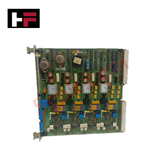
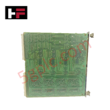
Product Details
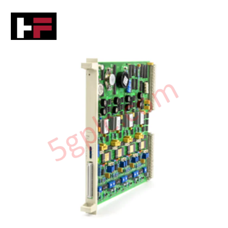
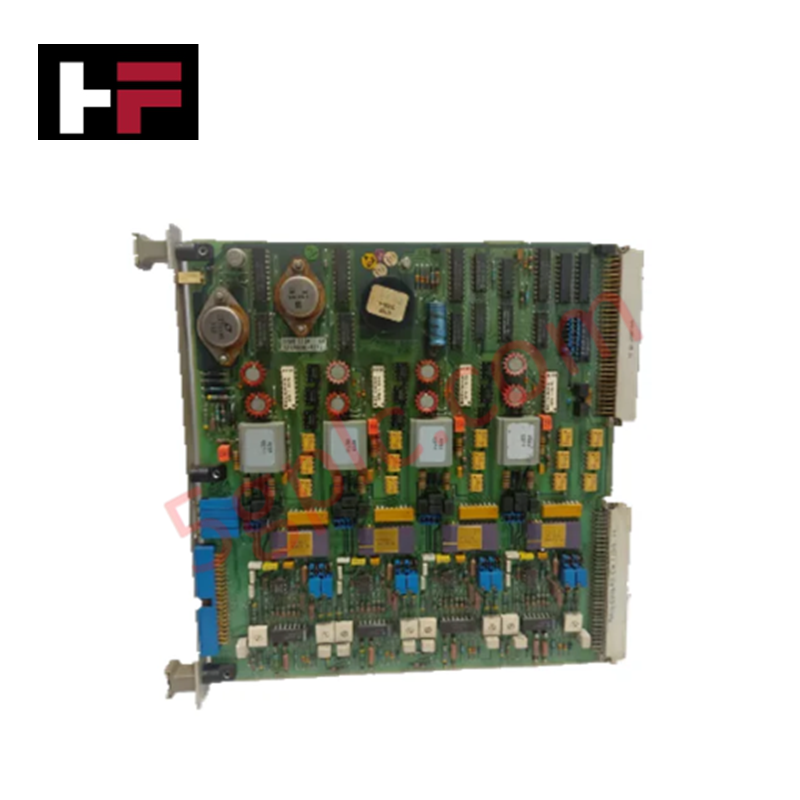
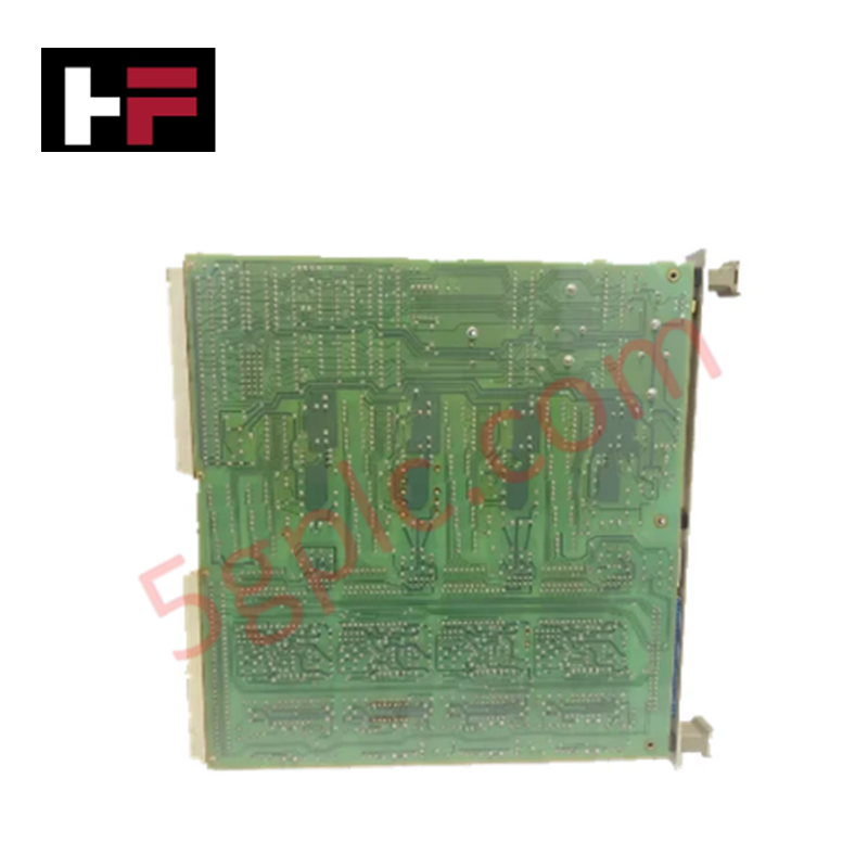
The ABB 57120001-AT, also cataloged as the DSAO 110 Analog Output Module, operates as a dedicated hardware component for isolated variable loop command control within ABB automation systems.
Hardware Specifications
| Parameter | Specification |
| Model | DSAO 110 (Product ID: 57120001-AT) |
| Brand | ABB |
| Origin | Sweden |
| Weight | 0.595 kg |
| Dimensions | 225 mm x 18 mm x 209.7 mm |
| Operating Temp | 0 to +55 deg C (Standard industrial parameters) |
| Power Consumption | System bus and loop generation dependent |
| Product Type | I-O Module |
| Channels | 4 analog output channels |
| Signal Configuration | 0-10 V, 0-20 mA |
| Base Accuracy | 0.05% |
| Electrical Isolation | Isolated channel architecture |
| WEEE Category | 5. Small Equipment (No External Dimension More Than 50 cm) |
| Battery Count | 0 |
Backplane Bus Communication Velocity and Signal Tracking
The module internal logic processes data conversions with a calibrated base accuracy of 0.05%, translating register commands directly from the main processor rack. This conversion pipeline interfaces with regional hardware buses while maintaining continuous compatibility with native backplane bus communication velocity frameworks. Output states update deterministically matching processor loop execution timings, ensuring that targeted 0-10 V and 0-20 mA signals track host values precisely without requiring localized firmware modification or decreasing the maximum I/O density scaling limit of the local termination group.
Frequently Asked Questions
Q: Does the galvanic isolation structure isolate individual output channels from each other?
A: Yes, the design provides an electrical isolation barrier separating the channel loops from the internal logic, preventing field-side ground loops from entering the backplane data bus lines.
Q: Can this module be directly interchanged with newer DSAO series configurations?
A: A full replacement requires updating the terminal hardware layout. Specifically, the combination of a DSAO 120A module and a DSTA 171 termination unit substitutes for the legacy DSAO 110 and DSTA 160 assembly, matching physical and electrical parameters after wire reconnection.
Q: Is manual voltage-to-current calibration required via jumpers prior to module hot-swap insertion?
A: Signal configurations for 0-10 V or 0-20 mA modes are handled via terminal wire landing points and controller software configuration settings. Ensure the rack section is powered down before making wire modifications or swapping the module.
Field Installation Guidelines
-
Terminal Block Configuration: Ensure correct wire termination based on the chosen output configuration (0-10 V or 0-20 mA). If utilizing a replacement front plate like the 29491274-11, verify terminal numbering before screw torque application.
-
Shield Grounding Topology: Connect analog signal loop shields to a single low-impedance copper master ground bar inside the control enclosure. Avoid dual grounding paths to prevent loop current errors on the 0.05% accuracy boundary.
-
Spatial Positioning and Airflow: Slot the module into the designated rack position vertically. The 18 mm component profile requires standard horizontal spacing clear of unvented inductive high-heat arrays to maintain proper cooling metrics.
-
Inductive Load Suppression: When driving proportional control valves or electro-hydraulic actuators with high inductance, run external suppressor loops across the field terminals to insulate the output channels from transient voltage reflections during step changes.
Additional Information
- 100% Genuine Parts: All products are original and authentic, ensuring reliable industrial performance.
- 30-Day Refund Guarantee: Return any in-stock item within 30 days in original, unopened packaging for a full refund (excluding shipping and fees).
- 12-Month Warranty: Covers defects in materials or workmanship; excludes misuse, normal wear, or unauthorized modifications.
- Worldwide Shipping: We ship via USPS, UPS, FedEx, and DHL. Delivery times vary by country and may be subject to customs or import fees.
- Support & Contact: Technical and warranty assistance is available anytime. Contact us here: Contact.
- Purchase Guidance: Check product specifications and compatibility carefully before ordering to ensure proper application.









Tech & Buying Guide

Static UPS vs. Rotary UPS: Technical Evaluation for Industrial Automation

Comprehensive Guide to Noise Types in Industrial Automation and Electronics

Mitigating Emergency Stop Spurious Trips in Industrial Control Systems
Emergency stop (E-Stop) pushbuttons serve as vital safety devices in factory automation and process control plants. Functional safety standards mandate normally-closed (NC) contact blocks to ensure fail-safe operation during wiring breaks or power outages. However, mechanical degradation over time can trigger unexpected spurious trips, halting production lines without an actual emergency. Understanding the underlying causes of mechanical contact failure allows automation engineers to implement robust, fault-tolerant safety circuits.