










Product Details
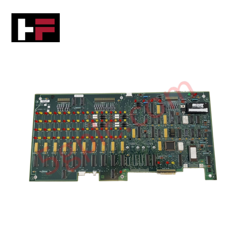
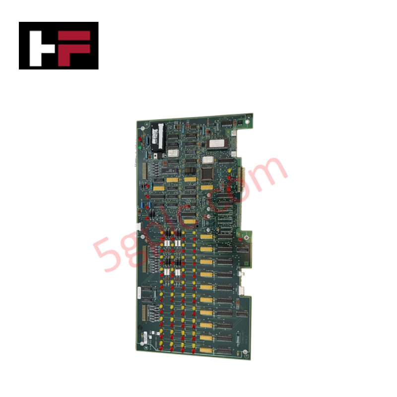
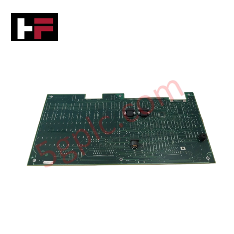
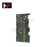
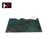
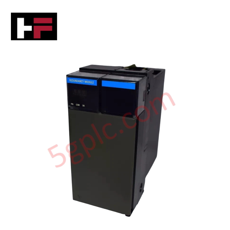
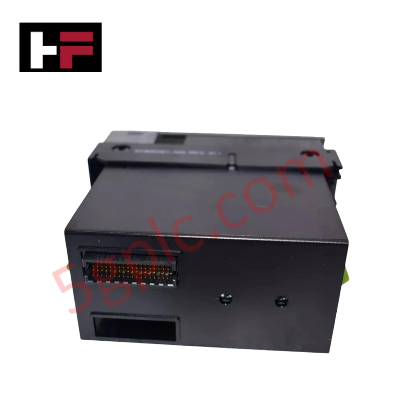
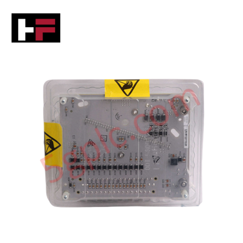
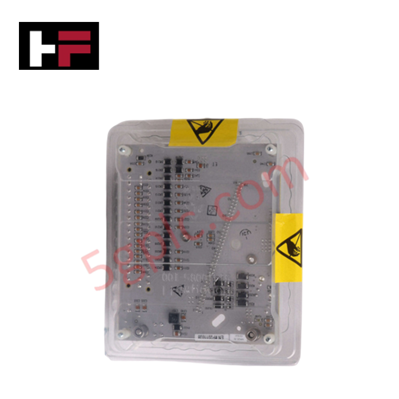
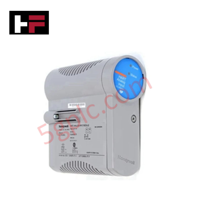
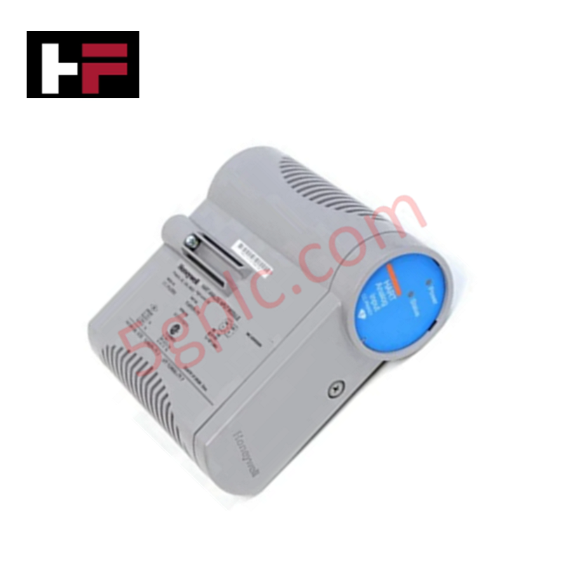
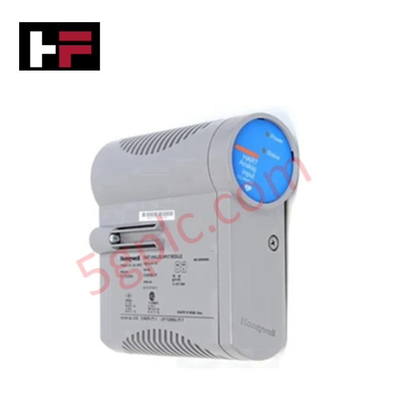
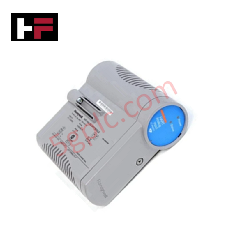
The Honeywell 51401952-100, also cataloged as the 51401952-100 Printed Circuit Board Assembly, operates as a dedicated hardware component for control system communication and interface processing within Honeywell Experion PKS and TDC 3000 platforms. It routes high-speed digital logic signals across proprietary backplane headers and manages bus arbitration between local processing units and field I/O racks.
Hardware Specifications
| Parameter | Specification |
|---|---|
| Model | 51401952-100 |
| Brand | Honeywell |
| Origin | USA |
| Weight | 0.6 kg |
| Dimensions | 270 mm x 200 mm |
| Operating Temp | -20 to 60 deg C |
| Power Consumption | Nominal 24 VDC bus feed |
| Product Type | Printed Circuit Board Assembly |
| System Compatibility | Honeywell Experion PKS, Honeywell TDC 3000 |
| Storage Temperature | -40 to 70 deg C |
| Relative Humidity | 5% to 95% RH (non-condensing) |
| PCB Construction | Multi-layer board with integrated EMI shielding |
| Connector Interface | Honeywell proprietary backplane and module connectors |
DCS Process Control & Channel-to-Channel Isolation
Designed for integration into high-density DCS racks, the multi-layer printed circuit board incorporates dedicated power planes and ground isolation barriers to prevent cross-talk during concurrent signal execution. The internal plane layout maintains strict channel-to-channel isolation across digital signal paths, suppressing transient high-frequency voltage spikes generated by external field loops. This physical trace separation preserves signal integrity for parallel 4-20 mA HART loop protocol communications and fieldbus controller interfaces tied to the local backplane.
Frequently Asked Questions
Q: Does this circuit board support direct hot-swapping while the host backplane is fully energized?
A: Insertion or removal must follow standard system rack procedures; unseating the board while the 24 VDC bus is active can induce bus communication faults or pin arcing unless the slot is software-inhibited.
Q: How is thermal dissipation handled across the multi-layer board structure?
A: Heat generated by onboard integrated circuits is dissipated through internal copper power ground planes and passive convection across the standard rack chassis format.
Field Installation Guidelines
- Disconnect all 24 VDC power feeds to the targeted rack rack chassis before inserting or removing the printed circuit board assembly.
- Wear a grounded wrist strap attached to the cabinet chassis ground point to prevent electrostatic discharge (ESD) damage to surface-mount components.
- Align the board edges with the card guide rails inside the rack enclosure before sliding the assembly inward.
- Press firmly on the card levers to fully seat the proprietary backplane connectors into the bus motherboard socket.
- Fasten all retaining screws on the front faceplate to ensure structural stability and continuous chassis frame grounding.
Additional Information
- 100% Genuine Parts: All products are original and authentic, ensuring reliable industrial performance.
- 30-Day Refund Guarantee: Return any in-stock item within 30 days in original, unopened packaging for a full refund (excluding shipping and fees).
- 12-Month Warranty: Covers defects in materials or workmanship; excludes misuse, normal wear, or unauthorized modifications.
- Worldwide Shipping: We ship via USPS, UPS, FedEx, and DHL. Delivery times vary by country and may be subject to customs or import fees.
- Support & Contact: Technical and warranty assistance is available anytime. Contact us here: Contact.
- Purchase Guidance: Check product specifications and compatibility carefully before ordering to ensure proper application.
Tech & Buying Guide

Static UPS vs. Rotary UPS: Technical Evaluation for Industrial Automation

Comprehensive Guide to Noise Types in Industrial Automation and Electronics

Mitigating Emergency Stop Spurious Trips in Industrial Control Systems
Emergency stop (E-Stop) pushbuttons serve as vital safety devices in factory automation and process control plants. Functional safety standards mandate normally-closed (NC) contact blocks to ensure fail-safe operation during wiring breaks or power outages. However, mechanical degradation over time can trigger unexpected spurious trips, halting production lines without an actual emergency. Understanding the underlying causes of mechanical contact failure allows automation engineers to implement robust, fault-tolerant safety circuits.