Product Details
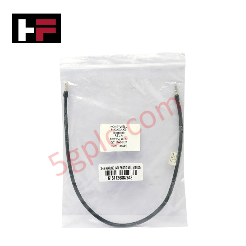
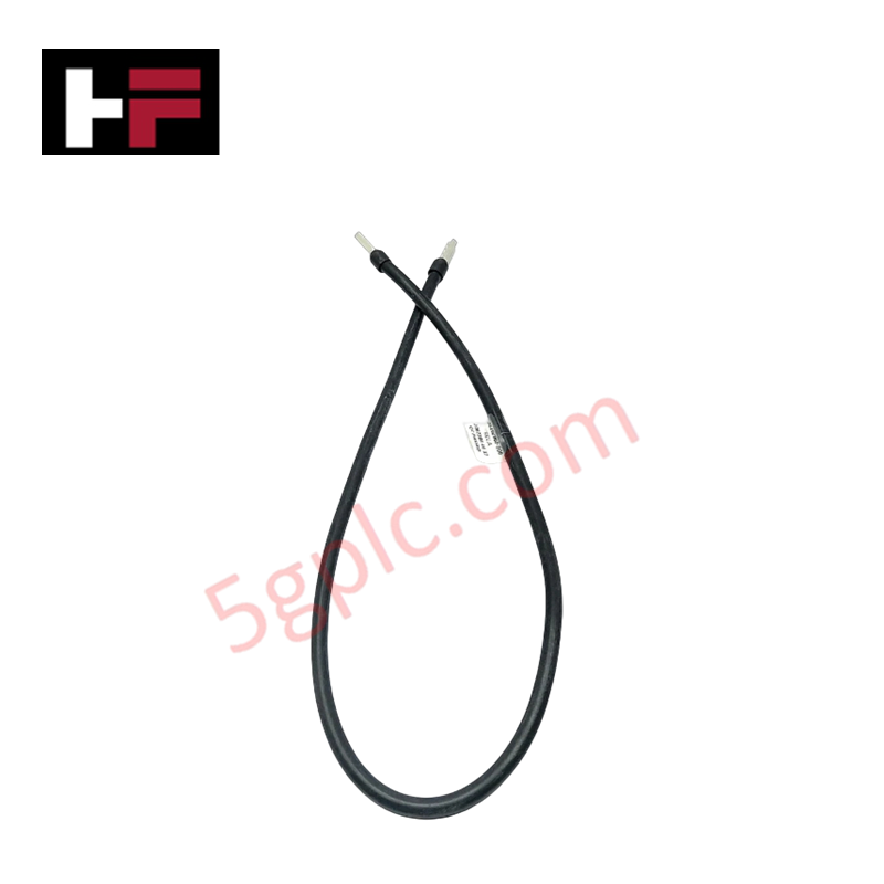
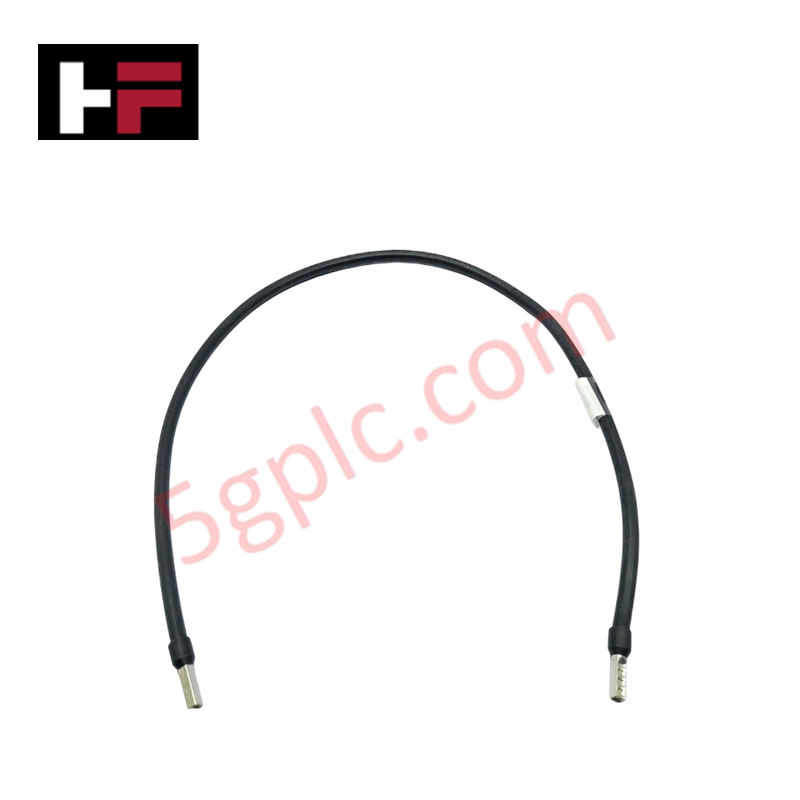
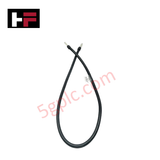
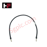
The Honeywell 51202902-200 serves as the primary 51202902 Shielded PLC Communication Cable utilized to execute real-time discrete or analog data transmission across Honeywell distributed control system platforms. The assembly establishes low-impedance physical signal paths through tinned copper conductors to route control bus sequences between processing nodes and terminal panels.
Hardware Specifications
| Parameter | Specification |
|---|---|
| Model | 51202902-200 |
| Brand | Honeywell International Inc. |
| Origin | USA |
| Weight | 0.2 kg |
| Dimensions | Extended length (typically 5-10 meters) |
| Operating Temp | -20 to +80 deg C |
| Power Consumption | Passive Component (Zero active load) |
| Cable Type | Shielded multi-core industrial communication cable |
| Conductor Material | Tinned copper |
| Insulation Material | PVC/ XLPE |
| Shielding Structure | Aluminum foil with braided shield |
| Characteristic Impedance | 120 ohms +-10% |
| Voltage Rating | 300 V |
| Storage Temperature | -40 to +85 deg C |
| Outer Jacket | Industrial-grade protective jacket |
Honeywell DCS Channel-to-Channel Isolation Parameters
The hardware assembly relies on its multi-core PVC/XLPE dielectric insulation matrix to assist the host architecture in maintaining standardized channel-to-channel isolation limits. Combined with an aluminum foil and braided shield layer, this topology suppresses inductive cross-talk and provides common-mode noise rejection across the 120 ohms transmission line, preventing voltage spikes from degrading loop values.
Frequently Asked Questions
Q: Can this communication cable be unlatched while the linked PLC modules are actively running processing loops?
A: No, the connection interface lacks live hot-swap disconnect protection; standard operating protocol requires the related rack power supply to be isolated prior to cable removal to prevent digital bus crashes.
Q: What is the physical limitation imposed by the 120 ohms characteristic impedance?
A: The 120 ohms +-10% characteristic impedance matches standard high-speed serial and differential bus standards, requiring termination resistors at network ends to neutralize data reflections.
Field Installation Guidelines
- Route the shielded multi-core cable through dedicated instrument trays, ensuring physical spacing from high-voltage motor starters or AC switchgear lines to minimize noise induction.
- Maintain standard bending radius tolerances during layout routing to prevent elongation of the aluminum foil or deformation of the braided shield structure.
- Terminate the integrated shield drain element to a single low-impedance master instrument earth bar within the local panel enclosure.
- Verify all terminal clamping hardware matches standard tension requirements to resist ongoing industrial ambient vibration breakdown.
Additional Information
- 100% Genuine Parts: All products are original and authentic, ensuring reliable industrial performance.
- 30-Day Refund Guarantee: Return any in-stock item within 30 days in original, unopened packaging for a full refund (excluding shipping and fees).
- 12-Month Warranty: Covers defects in materials or workmanship; excludes misuse, normal wear, or unauthorized modifications.
- Worldwide Shipping: We ship via USPS, UPS, FedEx, and DHL. Delivery times vary by country and may be subject to customs or import fees.
- Support & Contact: Technical and warranty assistance is available anytime. Contact us here: Contact.
- Purchase Guidance: Check product specifications and compatibility carefully before ordering to ensure proper application.




Tech & Buying Guide

Importance of Safety Barriers in PLC and DCS Control Systems

Static UPS vs. Rotary UPS: Technical Evaluation for Industrial Automation