












Product Details
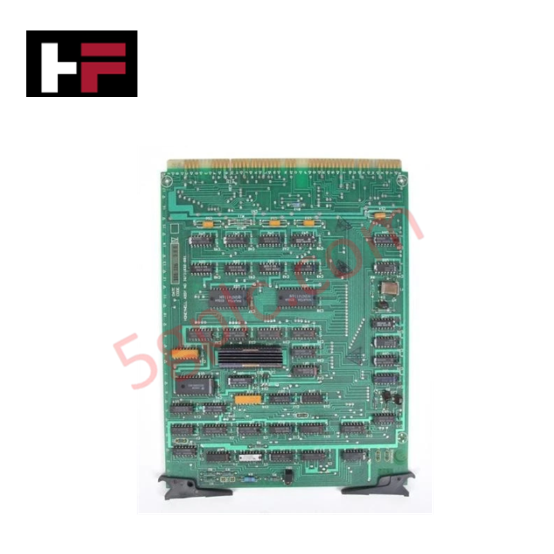
The Honeywell 30731832-001, also cataloged as the 30731832-001 Processor Module, operates as a dedicated hardware component for centralized logic processing and data communication within Honeywell TDC 2000 networks.
Hardware Specifications
| Parameter | Specification |
|---|---|
| Model | 30731832-001 |
| Brand | Honeywell |
| Origin | USA / Global Manufacturing |
| Weight | 0.8 kg |
| Dimensions | 11.5 x 8.5 x 4.2 cm |
| Operating Temp | 0 to +60 deg C |
| Power Consumption | Powered via 24 VDC rack backplane |
| Module Type | Processor Module |
| System Compatibility | Honeywell TDC 2000 |
| Status Diagnostic | Single Status LED |
| Compatible Host Assemblies | CB, RCD, HLPIU, LLPIU, LEPIU, Operator Stations |
Channel-to-Channel Isolation and Highway Bus Processing
The 30731832-001 Processor Module executes deterministic control algorithm loops and manages digital signal synchronization across the backplane bus. Internal power conditioning circuits draw 24 VDC directly from the rack backplane assembly to feed onboard processing logic.
To maintain system integrity across multi-card chassis configurations, the module incorporates channel-to-channel isolation and differential noise filtering along backplane communication pathways. Onboard self-diagnostic routines drive the front-panel status LED to indicate real-time module operational states and bus synchronization errors without requiring external test equipment.
Frequently Asked Questions
Q: How is primary operating power supplied to the 30731832-001 processor module?
A: Power is delivered directly from the 24 VDC rack backplane bus through the rear edge-card interface connectors.
Q: Which TDC 2000 system assemblies support the insertion of this processor module?
A: The module is designed for direct integration into CB, RCD, HLPIU, LLPIU, LEPIU racks, and operator stations.
Q: What function does the front-panel LED indicator perform?
A: The single LED serves as a primary diagnostic indicator for operational status monitoring and fault identification.
Field Installation Guidelines
- Verify that main rack power is turned off before seating or extracting the processor card from the backplane assembly.
- Use a grounded ESD wrist strap during handling to prevent electrostatic damage to surface-mount components.
- Ensure physical alignment along card cage guide channels prior to applying firm pressure to seat backplane connectors.
- Maintain unobstructed air circulation around the rack enclosure to prevent thermal buildup within industrial control cabinets.
Additional Information
- 100% Genuine Parts: All products are original and authentic, ensuring reliable industrial performance.
- 30-Day Refund Guarantee: Return any in-stock item within 30 days in original, unopened packaging for a full refund (excluding shipping and fees).
- 12-Month Warranty: Covers defects in materials or workmanship; excludes misuse, normal wear, or unauthorized modifications.
- Worldwide Shipping: We ship via USPS, UPS, FedEx, and DHL. Delivery times vary by country and may be subject to customs or import fees.
- Support & Contact: Technical and warranty assistance is available anytime. Contact us here: Contact.
- Purchase Guidance: Check product specifications and compatibility carefully before ordering to ensure proper application.


Tech & Buying Guide

Demystifying the DDE Protocol in Legacy Industrial Automation Systems
Modern control systems rely heavily on seamless interprocess communication to exchange operational data between software programs. Microsoft first introduced the Dynamic Data Exchange (DDE) protocol in 1987 to enable real-time data sharing. In factory automation, DDE served as an early bridge between control software and Windows desktop applications. Therefore, understanding DDE mechanics provides crucial insights into how legacy industrial networks established software-level connectivity.

Demystifying CPU Communication Ports in Siemens PLC Architectures
Industrial automation relies heavily on robust data exchange between devices. Without seamless connectivity, field instruments, network switches, human-machine interfaces, and programmable logic controllers cannot coordinate effectively. Therefore, understanding the various CPU communication ports available in Siemens hardware ensures efficient factory automation design and seamless system integration.

Mastering the Siemens PLC Scan Cycle: How the CPU Executes Automation Programs
Industrial automation relies heavily on programmable logic controllers (PLCs) to manage complex manufacturing processes. Many engineers dive straight into programming without mastering the underlying architecture. However, understanding how a PLC CPU executes a program ensures reliable system design. Therefore, mastering the scan cycle optimizes both performance and troubleshooting in modern control systems.