
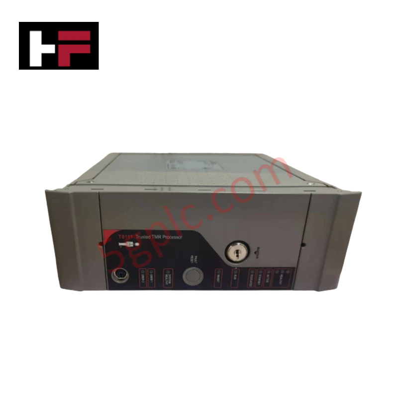
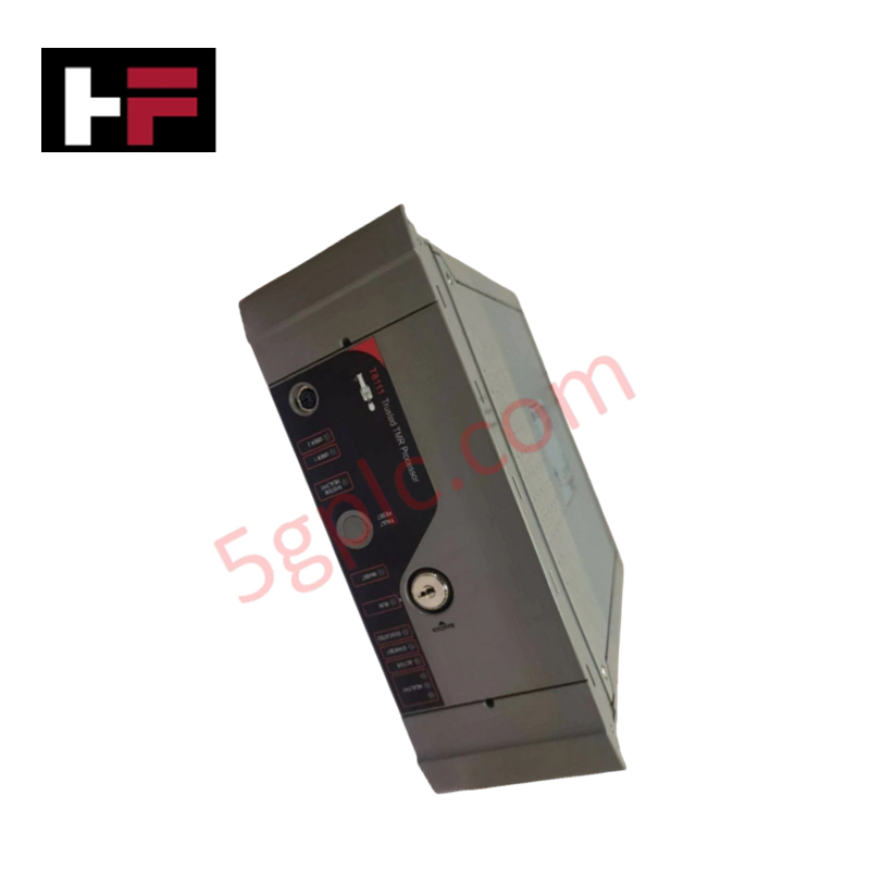
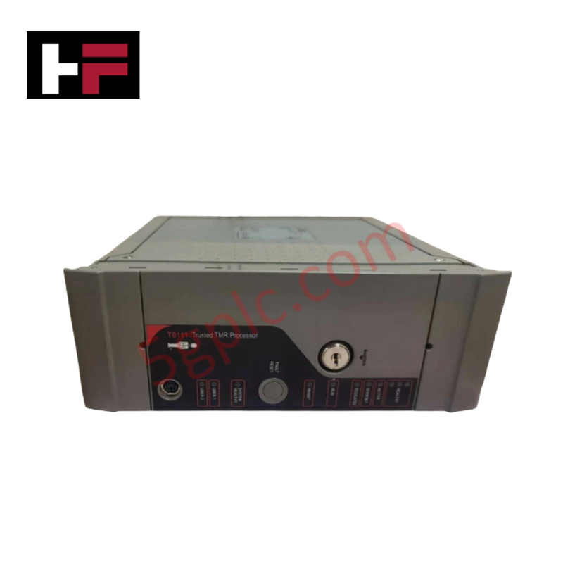
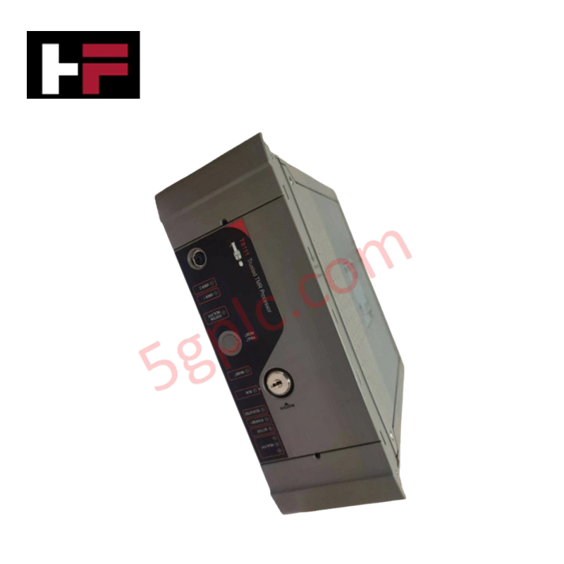
Product Details
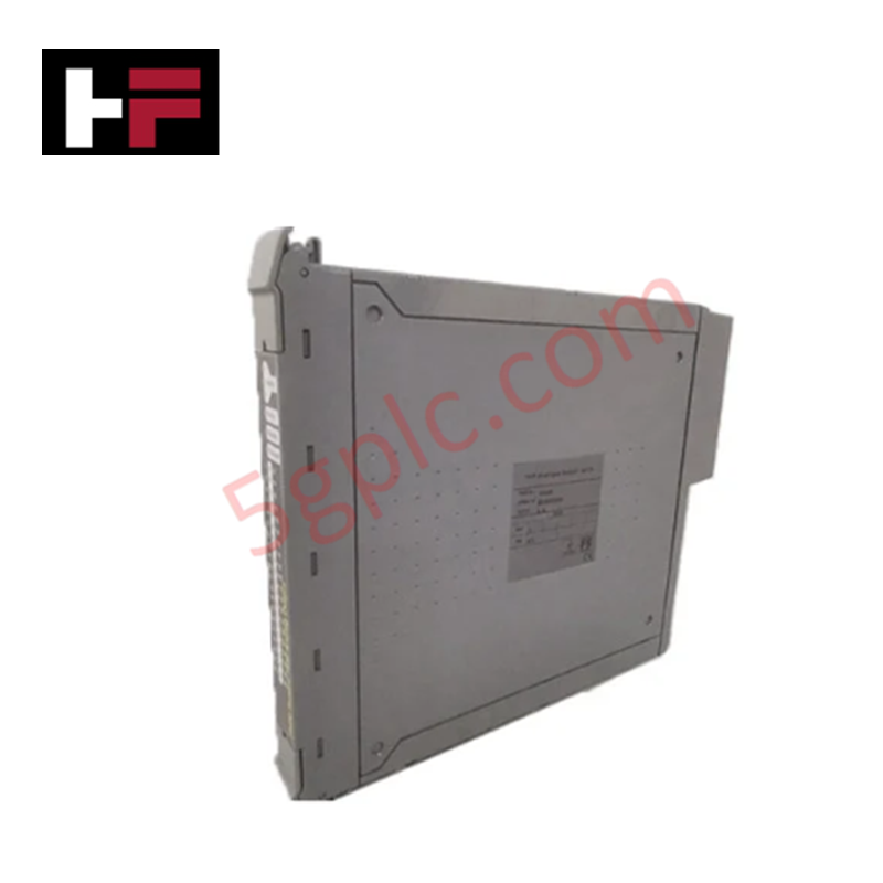
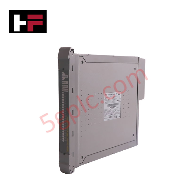
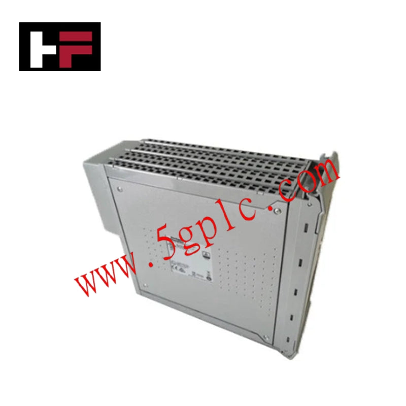
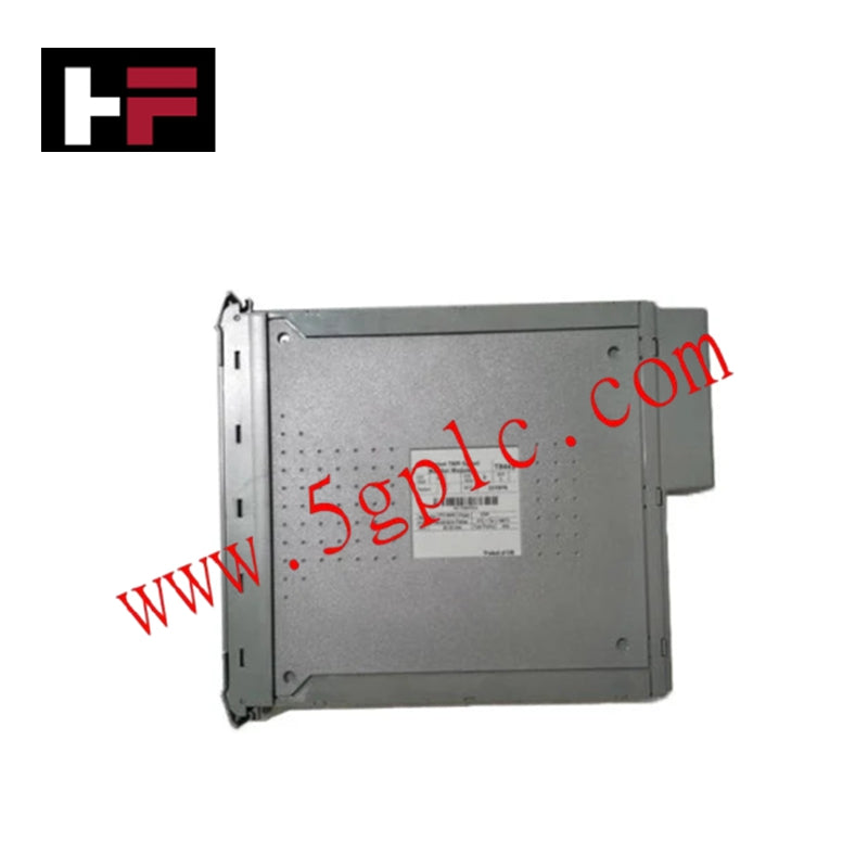
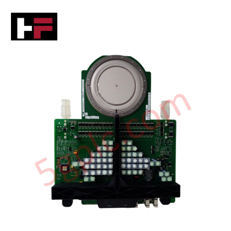
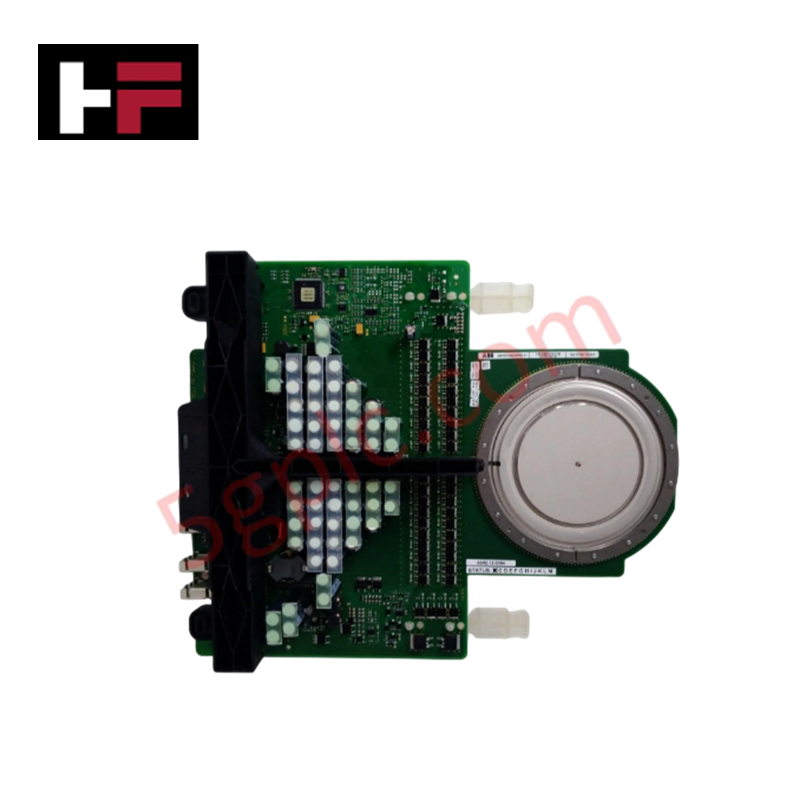
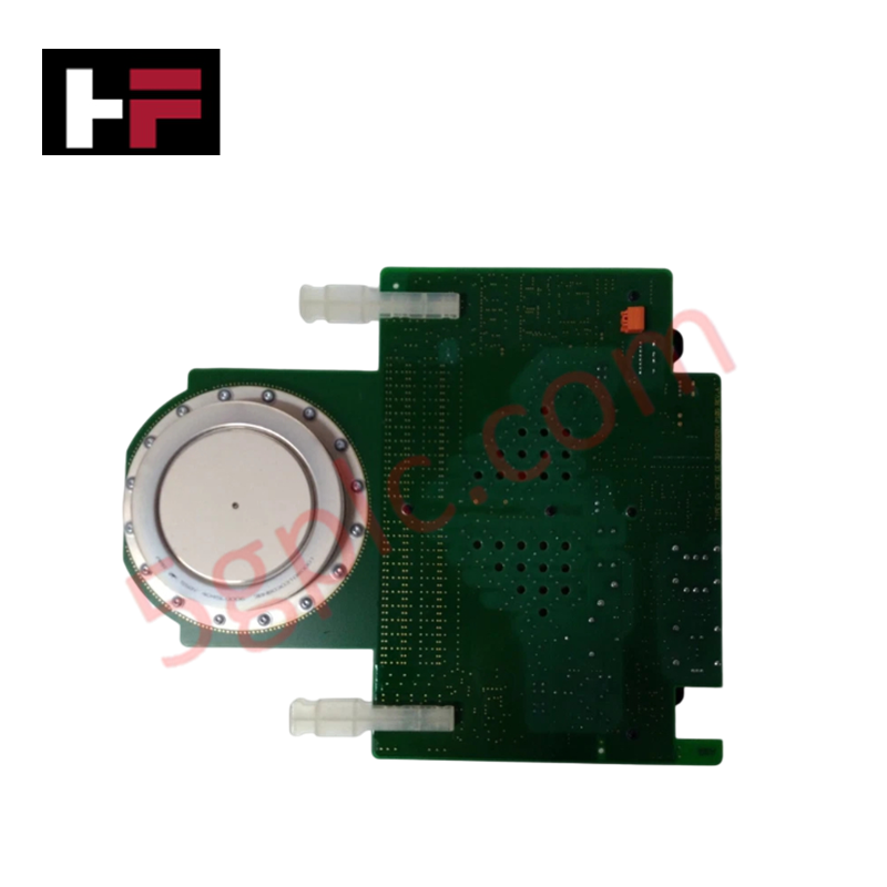
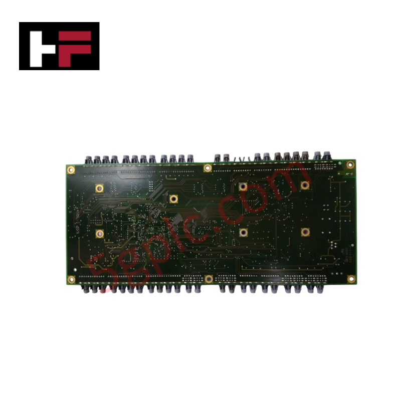
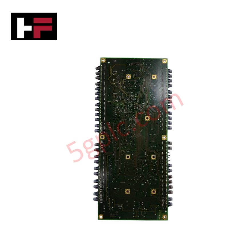
The ABB 3BHE014105R0001 5SHY3545L0020, also cataloged as the 3BHE014105R0001 IGCT Module, operates as a dedicated hardware component for high-power semiconductor switching within power generation and electrical drive systems. The device provides direct electrical execution, managing a rated voltage of 3300 V and a rated current of 1800 A via an integrated Integrated Gate-Commutated Thyristor wafer. Encapsulated in a Press-Pack S4 housing with an integrated NTC 10 kOhm temperature sensor, the unit routes gate turn-on and turn-off pulses locally to regulate power flow across industrial energy platforms.
Hardware Specifications
| Parameter | Specification |
|---|---|
| Model | 3BHE014105R0001 5SHY3545L0020 5SXE080166 |
| Brand | ABB |
| Origin | Technical specifications determine final factory origin |
| Weight | Heavy-duty press-pack assembly configuration dependent |
| Dimensions | Press-Pack S4, 122 mm x 140 mm x 38 mm |
| Operating Temp | -40 to +150 deg C (Junction Temperature) |
| Power Consumption | Switch-dependent; Eon <= 650 mJ, Eoff <= 550 mJ @ 1500 V / 1800 A |
| Rated Voltage (VCES) | 3300 V |
| Rated Current (IC) | 1800 A @ 90 deg C |
| On-State Voltage Drop | <= 1.5 V (typical) |
| Thermal Resistance | Rth = 0.015 K/W (Junction-to-Case) |
| Isolation Voltage | 12 kV AC, 1 min (50 Hz) |
| Integrated Monitoring | NTC 10 kOhm temperature sensor, +/-1 deg C accuracy |
| Certifications | UL 1557, IEC 60747-9 |
Profinet / EtherNet/IP Deterministic Networks Mapping
The high-power gate unit driver integrated within the module structures transient gating energy independently from external supervisory loops. Firmware flash compatibility across matching control boards maintains strict gate commutation velocity, ensuring that heavy dynamic load shifts do not propagate noise into the low-voltage control backplane bus. The localized thermal metric from the NTC 10 kOhm sensor can be digitized and mapped directly to Profinet / EtherNet/IP deterministic networks, enabling microsecond monitoring of switching energy boundaries during continuous 1800 A commutation cycles.
Frequently Asked Questions
Q: What are the backplane or external drive limitations regarding firmware flash compatibility for this IGCT gate unit?
A: The gate control board attached to the press-pack must match the exact hardware revision of the master excitation or drive controller. Mismatched firmware profiles will lead to incorrect gate pulse timing, violating the specified Eon and Eoff energy bounds and risking commutation failure.
Q: Can this module be hot-swapped while the primary 3300 V bus is de-energized but the 12 kV AC isolation boundaries are active?
A: No. The press-pack architecture relies on exact mechanical clamping force and absolute isolation from all voltage potentials before servicing. No part of the control wiring or gate interface can be disconnected while any auxiliary power or high-voltage lines are connected to the module group.
Field Installation Guidelines
- Mechanical Clamping Pressure: Install the Press-Pack S4 module within an approved high-pressure clamping fixture to ensure symmetrical contact resistance across the upper and lower poles, maintaining the Rth 0.015 K/W thermal boundary.
- Gate Driver Fiber Isolation: Route all optical gating lines through dedicated separation tracks to minimize risk of physical bending damage or distortion to the light signals.
- NTC Signal Wiring: Connect the integrated NTC 10 kOhm monitoring terminals using shielded twisted-pair conductors, terminating the braid to earth ground at the cabinet entry bulkhead only.
Additional Information
- 100% Genuine Parts: All products are original and authentic, ensuring reliable industrial performance.
- 30-Day Refund Guarantee: Return any in-stock item within 30 days in original, unopened packaging for a full refund (excluding shipping and fees).
- 12-Month Warranty: Covers defects in materials or workmanship; excludes misuse, normal wear, or unauthorized modifications.
- Worldwide Shipping: We ship via USPS, UPS, FedEx, and DHL. Delivery times vary by country and may be subject to customs or import fees.
- Support & Contact: Technical and warranty assistance is available anytime. Contact us here: Contact.
- Purchase Guidance: Check product specifications and compatibility carefully before ordering to ensure proper application.


Tech & Buying Guide

Mastering VFD Braking Theory and Mechanical Brake Sequencing in Industrial Automation
In industrial automation, variable frequency drives (VFDs) regulate motor speed and torque across manufacturing plants and material handling systems. However, certain heavy-duty applications experience external loads that can rotate the motor shaft without an active command. For instance, gravity pulls loads downward in unanchored hoisting equipment. Therefore, engineers integrate mechanical brakes with VFD logic to maintain absolute safety and prevent structural damage or personnel injury during shutdowns.

Optimizing Tank Level Control Using Proportional Algorithms in PLC Systems
Industrial automation engineers frequently encounter liquid level regulation challenges across diverse process plants. Traditional ON-OFF control mechanisms often disrupt system stability due to abrupt actuator switching. Therefore, upgrading to closed-loop architectures like proportional control yields smoother responses. In a typical PLC environment, such as Siemens TIA Portal, engineers utilize closed-loop feedback to minimize process errors without requiring full PID complexity.

Understanding Why Your PLC Enters Stop Mode: Causes and Troubleshooting
In industrial automation, programmable logic controllers (PLCs) serve as the core intelligence of modern factory automation and distributed control systems (DCS). Understanding how a PLC transitions between modes is vital for maintenance engineers. Typically, a PLC operates across four primary modes: Run, Stop, Start-Up, and Hold. When power is applied, the system immediately boots into Stop mode before initiating the Start-Up sequence. If the controller encounters a critical error during execution, it automatically reverts to Stop mode to prevent equipment damage. Therefore, monitoring these state transitions helps technicians maintain high system availability.