










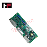
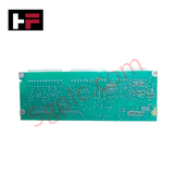
Product Details
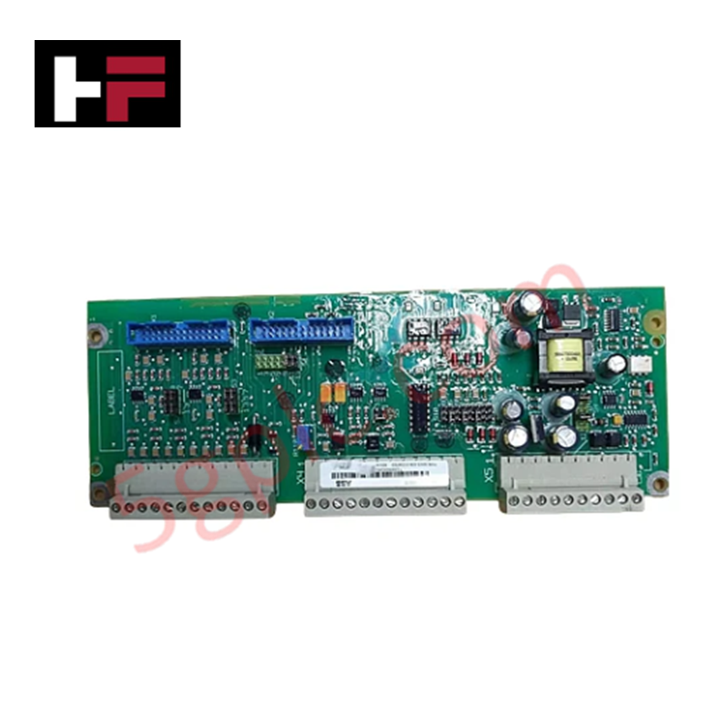
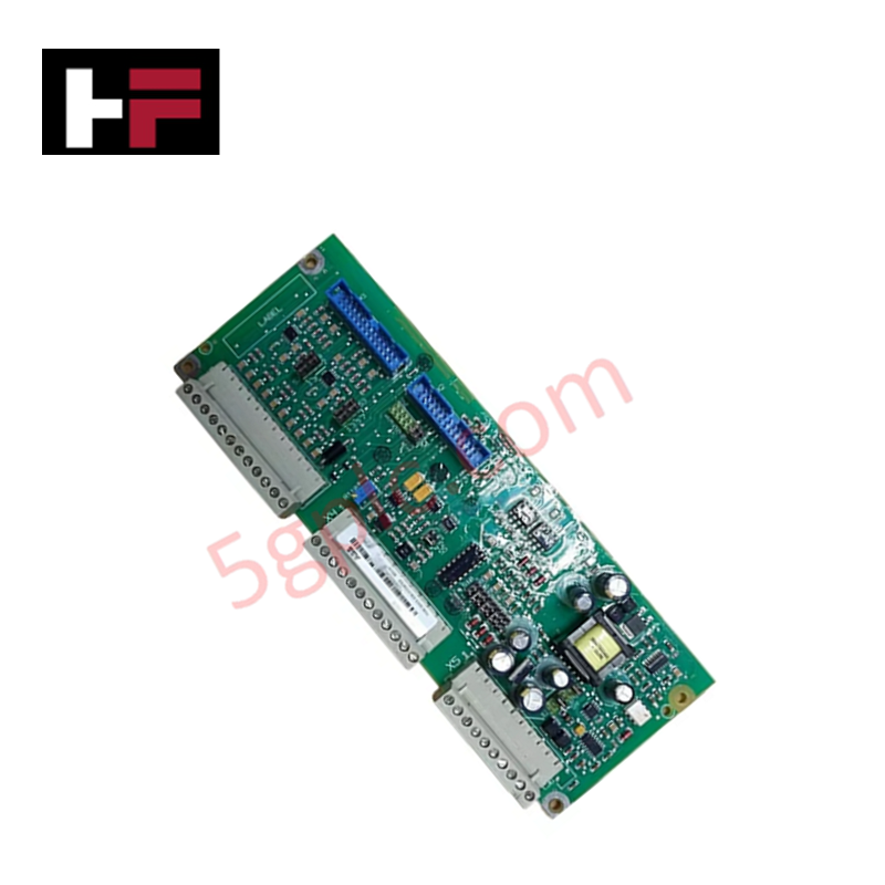
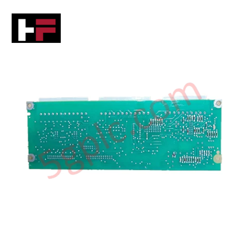
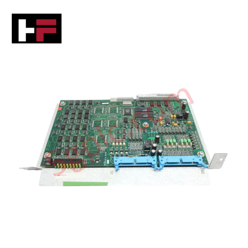
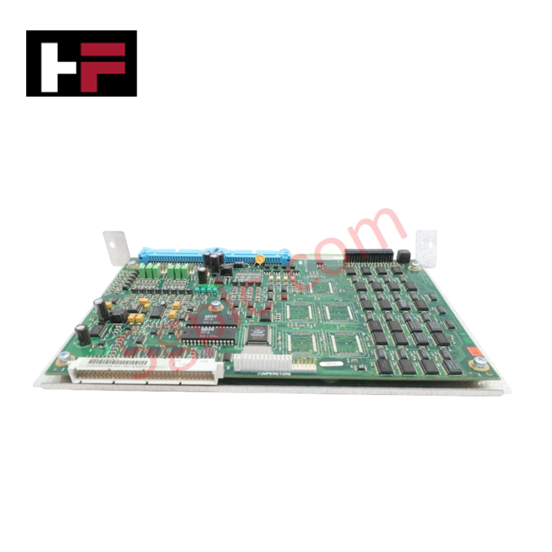
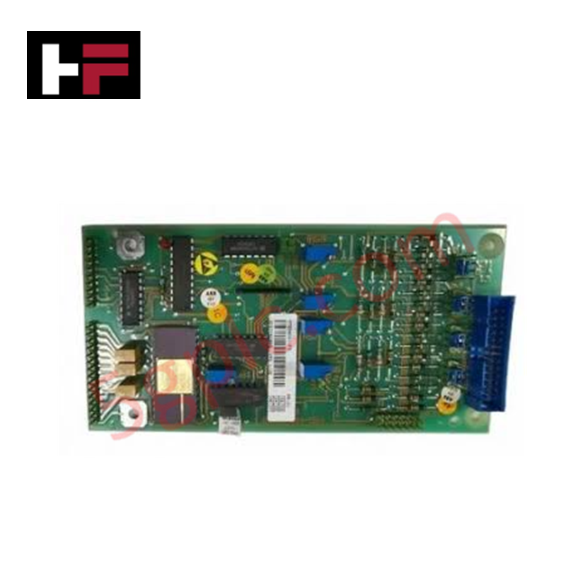
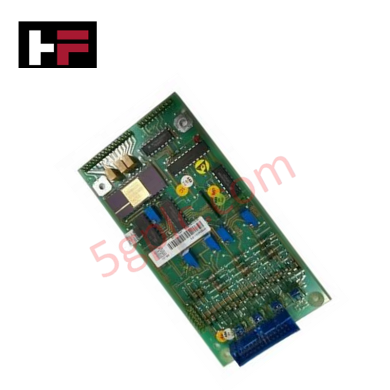
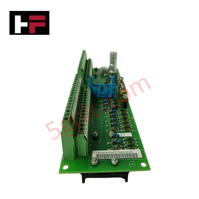
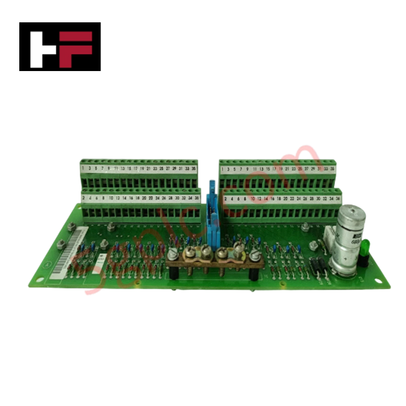
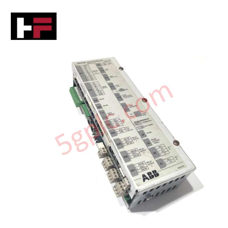
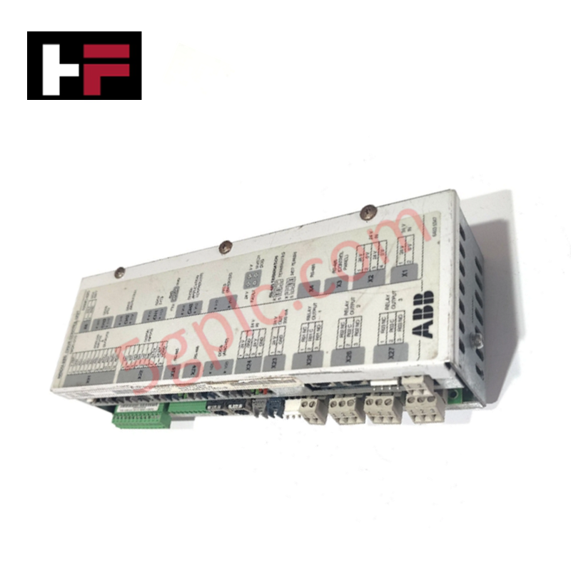
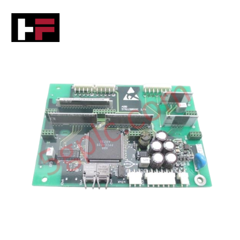
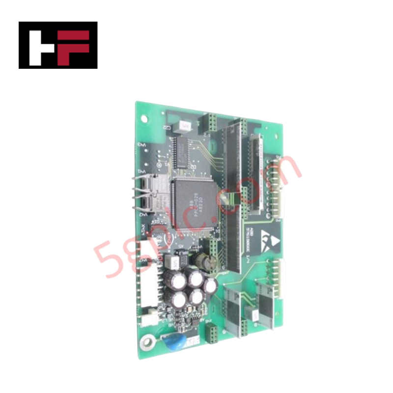
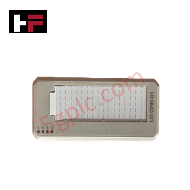
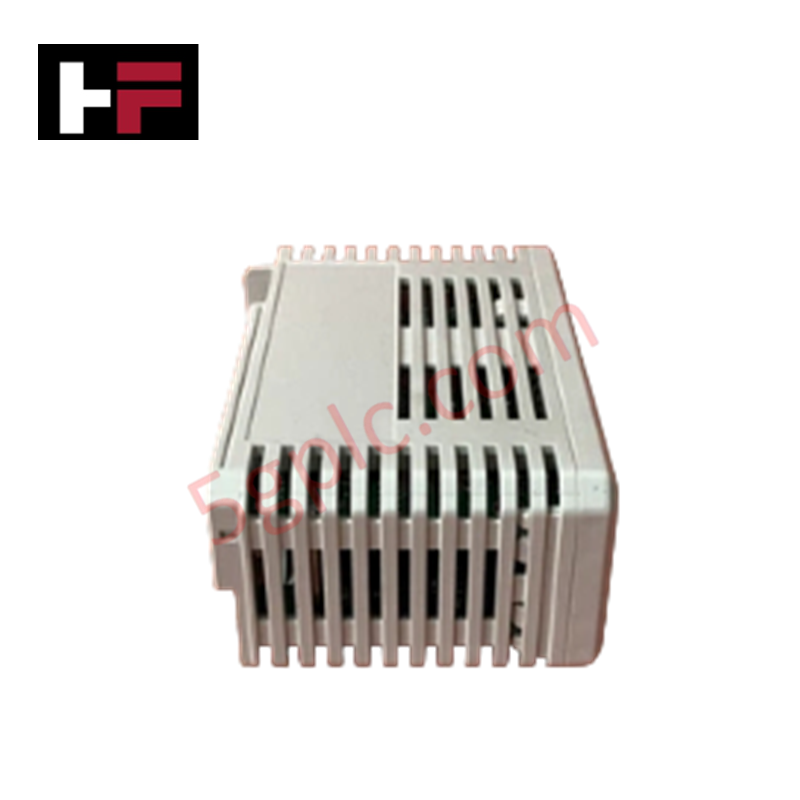
The ABB SDCS-IOB-3 3BSE004086R0001, also cataloged as the SDCS-IOB-3 I/O Connection Board, operates as a dedicated hardware component for peripheral signal conditioning and interface execution within ABB DC drive control assemblies.
Hardware Specifications
| Parameter | Specification |
|---|---|
| Model | SDCS-IOB-3 (Product ID: 3BSE004086R0001) |
| Brand | ABB |
| Origin | Finland |
| Weight | 0.19 kg |
| Dimensions | Standard industrial interface card form factor |
| Operating Temp | 0 to +55 deg C (Standard environment tracking) |
| Power Consumption | Derived via drive control interface links |
| Product Type | I/O Connection Boards |
| Part Type | New |
| Minimum Order Quantity | 1 piece |
Profinet / EtherNet/IP Deterministic Networks and Firmware Flash Compatibility
The architectural circuit layout of the SDCS-IOB-3 channels physical digital and analog field lines into the primary drive controller registers. By standardizing internal signal propagation loops, the board buffers IO transitions to maintain constant backplane bus communication velocity across the internal network. This electrical shielding preserves configuration synchronization metrics when mapping drive runtime registries into external Profinet / EtherNet/IP deterministic networks through communication adapters. The component configuration ensures baseline firmware flash compatibility, preventing local variable state updates from introducing processing jitter or limiting plant-wide I/O density scaling.
Frequently Asked Questions
Q: Does the physical design of the SDCS-IOB-3 interface support live hot-swap replacement under power?
A: No. The board maintains active connections with encoder tracking and analog feedback scaling loops. Unmounting or seating the module while the power rails are live can cause diagnostic tracking drops, induce transient faults, and halt the host drive assembly.
Q: How are field wiring signals isolated from the primary processor registers through this board?
A: The board topology uses dedicated component separation to isolate high-frequency noise profiles. It passes clean signal states back to the master processing unit over synchronous ribbon connection tracks.
Q: What defines the baseline firmware calibration sequence for a newly installed SDCS-IOB-3?
A: The card functions as a passive/semi-passive hardware signal routing layer. It requires no local firmware flash compatibility configuration; parameter definition and loop scaling coefficients are held directly within the main motor control board memory.
Field Installation Guidelines
- Chassis Mounting Stability: Align the board onto the designated standoffs inside the converter cabinet. Tighten all mechanical fasteners to create a rigid physical ground bond to the metal backplate.
- Shielding Matrix Interface: Ground the copper braids of all incoming signal cables to the enclosure earthing strip. Proper shield terminations prevent variable speed drive harmonics from corrupting low-voltage analog loops.
- Ribbon Conductor Alignment: Seat the flat ribbon communication wires orthogonally into the onboard sockets. Confirm that the lateral plastic retaining clips snap locked over the connector housing to prevent vibration loose-contacts.
- Separation of Signal Tracks: Route all low-voltage control signals away from high-power AC input lines or motor output cable trays to avoid electromagnetic induction.
Additional Information
- 100% Genuine Parts: All products are original and authentic, ensuring reliable industrial performance.
- 30-Day Refund Guarantee: Return any in-stock item within 30 days in original, unopened packaging for a full refund (excluding shipping and fees).
- 12-Month Warranty: Covers defects in materials or workmanship; excludes misuse, normal wear, or unauthorized modifications.
- Worldwide Shipping: We ship via USPS, UPS, FedEx, and DHL. Delivery times vary by country and may be subject to customs or import fees.
- Support & Contact: Technical and warranty assistance is available anytime. Contact us here: Contact.
- Purchase Guidance: Check product specifications and compatibility carefully before ordering to ensure proper application.
Tech & Buying Guide

Understanding PLC Digital Output Types: Relay, Transistor, and Triac Explained
Programmable Logic Controllers (PLCs) form the backbone of modern industrial automation systems. They interface directly with field devices such as solenoid valves, indicator lights, motor starters, and interposing relays. Selecting the correct digital output module ensures high system availability and long hardware service life.

Understanding VFD Mechanical Brake Logic and Control in Industrial Automation
Variable Frequency Drives (VFDs) play a crucial role in modern industrial automation by controlling motor speed, torque, and acceleration. However, high-inertia loads and vertical lifting systems require precise mechanical braking logic to ensure operational safety and prevent equipment damage.

Why Programmable Logic Controllers Drop into Stop Mode: An Expert Analysis
Industrial automation systems rely heavily on Programmable Logic Controllers (PLCs) to maintain uninterrupted production. When a PLC unexpectedly shifts from Run to Stop mode, whole manufacturing lines stall.
As control systems evolve across modern factory automation, understanding the root causes of these interruptions helps engineers minimize costly downtime. This technical guide breaks down why PLCs trip into Stop mode and provides practical strategies to mitigate system faults.